
Abstract
Long cable runs between variable frequency drives (VFDs) and motors are among the most underestimated sources of premature equipment failure in industrial drive systems. When PWM switching voltages travel through cables exceeding 30–50 meters, impedance mismatches generate reflected voltage waves that can nearly double the DC bus voltage at the motor terminals. The resulting dV/dt stress accelerates winding insulation degradation, induces capacitive bearing currents, and triggers partial discharge events — all invisible to standard monitoring yet highly destructive over time.
A sine wave filter, installed at the VFD output, reconstructs the PWM waveform into a clean sinusoidal output before it reaches the cable. This eliminates reflected wave overvoltage, suppresses dV/dt to safe levels, and dramatically extends motor service life. For procurement engineers and system designers evaluating long-cable drive configurations, understanding the technical case for sine wave filtration is essential — not only to protect assets but to justify the investment through quantifiable reductions in downtime and maintenance cost.
The Electrical Problem — What Long Motor Cables Do to Your Drive System
Reflected Wave Phenomenon and dV/dt Overvoltage
Modern VFDs generate output voltage through pulse-width modulation (PWM), producing a series of fast-switching voltage pulses with rise times as short as 0.1–0.5 microseconds. When these pulses travel along a motor cable, the system behaves as a transmission line. At the motor terminals, the surge impedance of the cable (typically 50–150 Ω) mismatches dramatically with the motor’s input impedance (often 1–5 kΩ at high frequencies), causing the traveling wave to reflect back toward the drive.
This impedance mismatch produces a reflected voltage that superimposes on the incident wave. In worst-case conditions — particularly with cables beyond 30–50 meters and fast IGBT switching — the reflected voltage at the motor terminals can reach up to 1.8–2.0 times the DC bus voltage. For a standard 480 V system with a DC bus of approximately 680 V, peak voltages of 1,200–1,360 V at motor terminals are common. The cable length threshold at which this becomes critical depends on the drive’s switching speed; faster switching frequencies (≥ 4 kHz) lower the safe cable length considerably.
This overvoltage is not a transient anomaly — it occurs with every PWM pulse, potentially thousands of times per second.
Winding Insulation Stress and Bearing Current Damage
Repeated high-amplitude, fast-rising voltage pulses impose severe stress on motor winding insulation. The uneven voltage distribution across winding turns means the first few turns from the terminal bear a disproportionate share of each spike. Over time, this initiates partial discharge — small ionization events within micro-voids in the insulation — which erode the dielectric material progressively. The result is insulation breakdown that is cumulative, temperature-accelerated, and ultimately catastrophic.
Simultaneously, the high-frequency common-mode voltages generated by PWM switching create capacitive coupling between the motor shaft and frame. This drives high-frequency circulating currents through the bearings, causing EDM (Electrical Discharge Machining) bearing pitting — microscopic craters on the bearing race surface that produce vibration, noise, and accelerated wear. Bearing failures attributed to EDM are frequently misdiagnosed as lubrication failures, masking the true electrical root cause.
How a Sine Wave Filter Works — Technical Principles
LC Filter Topology and Output Waveform Reconstruction
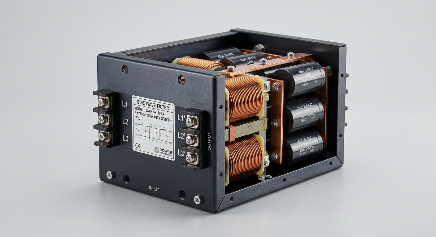
A sine wave filter is fundamentally an LC low-pass filter — a network of inductors and capacitors tuned to pass the fundamental drive frequency (typically 50 or 60 Hz) while attenuating the high-frequency PWM carrier and its harmonics. The filter is installed between the VFD output terminals and the motor cable.
The cutoff frequency of the LC network is engineered to sit well above the motor’s operating frequency but well below the VFD’s switching frequency — typically in the range of 300–800 Hz for drives switching at 2–16 kHz. This ensures the fundamental output voltage passes with minimal attenuation while the PWM switching transients are suppressed before they enter the cable. The result at the filter output is a smooth, near-sinusoidal voltage waveform with THDv (Total Harmonic Distortion, voltage) typically below 5%, compared to the raw PWM output which can exhibit THDv exceeding 80%.
This waveform reconstruction is the defining advantage over simpler mitigation devices: the cable and motor see a clean sine wave, not a chopped PWM signal.
dV/dt Suppression and Peak Voltage Clamping
Beyond waveform quality, the sine wave filter delivers quantifiable suppression of the two key stress parameters. The voltage rate of rise is reduced from the raw VFD output values of 5,000–20,000 V/μs to below 500 V/μs — the threshold recommended by IEC 60034-17 for standard motor windings. Peak voltage at the motor terminals is clamped to ≤ 1.0× the DC bus voltage, eliminating the reflected wave doubling effect entirely.
The following comparison illustrates the performance differential across filtering options:
| Parameter | No Filter | dV/dt Filter | Sine Wave Filter |
|---|---|---|---|
| Output Waveform | PWM square wave | Attenuated PWM | Clean sine wave |
| Peak Voltage (× DC bus) | Up to 2.0× | 1.2–1.5× | ≤ 1.0× |
| dV/dt | 5,000–20,000 V/μs | 500–2,000 V/μs | < 100–500 V/μs |
| Max. Safe Cable Length | 10–30 m | 50–150 m | Unlimited (practical) |
| Motor Insulation Requirement | Inverter-duty (NEMA MG1 Part 31) | Class F minimum | Standard Class B/F |
| Bearing Current Risk | High | Moderate | Low |
| Typical Application | Short-run, new inverter-duty motors | Medium cable runs | Long runs, legacy motors, sensitive environments |
Specifications, Compliance & Selection Criteria
Key Electrical Parameters for Procurement
When specifying a sine wave filter, procurement teams must verify the following core parameters against their system design:
- Rated current (A): Must match or exceed the motor’s full-load current with appropriate derating for ambient temperature and altitude.
- Switching frequency range: Confirm compatibility with the VFD’s carrier frequency. Filters designed for 4–8 kHz switching may underperform at 2 kHz or 16 kHz operation. Mismatched cutoff frequency design leads to either insufficient attenuation or excessive fundamental voltage drop.
- Insertion loss at fundamental frequency: Should be less than 3–5% to avoid measurable torque reduction at the motor shaft.
- Power loss / thermal dissipation: Sine wave filters introduce resistive and core losses — typically 0.5–1.5% of rated power. Enclosure thermal management must account for this heat load, particularly in sealed IP54/IP65 panel installations.
- Voltage rating: Must accommodate the system’s maximum DC bus voltage plus appropriate safety margin (e.g., 690 V AC rating for 480 V systems).
Applicable Standards and Motor Compatibility Requirements
The primary international standards governing VFD-motor cable stress are IEC 60034-17 (effects of sinusoidal supply voltage unbalance, voltage fluctuations, and waveform distortion on induction motors) and NEMA MG1 Part 31 (inverter-duty motor requirements for North American markets). NEMA MG1 Part 31 defines two tiers: motors capable of withstanding 3.1 p.u. peak voltage with ≤ 2,000 V/μs rise time, and those requiring ≤ 500 V/μs.
Standard motors (Class F insulation, IEC design) are not rated for the voltage spikes produced by long-cable VFD systems. A sine wave filter brings the drive output within the stress tolerance of standard motors, eliminating the mandatory upgrade to premium inverter-duty motors in retrofit scenarios. Where Class H insulation is already specified, the filter further extends life by operating the insulation well below its stress threshold. In food processing, marine, and pharmaceutical environments — where motor access for rewinding is difficult and contamination risks complicate maintenance — this protection is especially valuable.
Application Scenarios and Business Value
Industries and Drive Configurations That Demand Sine Wave Filters
Sine wave filters are not universally required for every VFD installation, but certain configurations make them effectively mandatory:
- Cable runs exceeding 50 meters: Pumping stations, HVAC systems in high-rise buildings, conveyor systems in large warehouses, and offshore platform motor drives routinely exceed this threshold.
- Retrofit applications: Replacing a direct-on-line starter with a VFD on an existing standard motor without upgrading the motor. The legacy motor’s insulation was never designed for PWM stress.
- Harsh environments: Marine, food & beverage, and chemical processing facilities where motor replacement requires equipment downtime, cleaning protocols, or confined-space access — making premature failure disproportionately expensive.
- Precision applications: CNC machining, medical equipment, and test stands where bearing noise and vibration from EDM pitting are operationally unacceptable.
Total Cost of Ownership — Downtime Prevention vs. Filter Investment
The financial case for a sine wave filter is straightforward when lifecycle costs are examined. A mid-size industrial motor (75–200 kW) costs $3,000–$15,000 to rewind and $500–$2,000 in labor for removal and reinstallation. Unplanned downtime in manufacturing environments typically costs $5,000–$50,000 per hour depending on production value. A motor failure that halts a production line for 8 hours generates losses that can exceed the capital cost of the drive system itself.
A quality sine wave filter for the same power range is priced at $800–$3,500 — a one-time investment with a service life matching the drive system (10–15 years). MTBF improvement for protected motors in long-cable applications is well-documented at 2–4× compared to unprotected installations. The payback period in most industrial scenarios is less than 12 months when a single avoided motor failure is factored in.
FAQ
1. What is the minimum cable length at which a sine wave filter becomes necessary for a standard VFD-motor system?
The commonly cited threshold is 30–50 meters, but the actual critical length depends on the VFD’s switching frequency and rise time. At 8 kHz switching with sub-microsecond rise times, reflected wave doubling can occur on cables as short as 15–20 meters. For drives with adjustable switching frequency, consult the drive manufacturer’s cable length derating curves.
2. Can a sine wave filter be used with an existing standard-efficiency motor, or is an inverter-duty motor required?
Yes — this is one of the primary use cases for a sine wave filter. By reducing peak voltage to ≤ 1.0× DC bus and dV/dt to below 500 V/μs, the filter brings the electrical stress within the tolerance of standard IEC motors. An inverter-duty motor upgrade is not required when a properly specified sine wave filter is installed.
3. How does a sine wave filter differ from a dV/dt filter, and when is each the appropriate choice?
A dV/dt filter limits the voltage rise rate but does not reconstruct a sinusoidal waveform — peak voltages may still reach 1.2–1.5× the DC bus. It is appropriate for cable lengths of 50–150 meters with inverter-duty motors. A sine wave filter fully eliminates the reflected wave problem, making it the correct choice for cable runs beyond 100 meters, standard motor retrofits, and applications where bearing current or audible noise is a concern.
Conclusion
Long motor cables transform a routine VFD installation into a high-stress electrical environment. The reflected wave phenomenon, dV/dt overvoltage, and EDM bearing currents that result from impedance mismatch are not theoretical concerns — they are measurable, progressive, and responsible for a significant share of premature motor failures in industrial facilities worldwide.
A sine wave filter addresses all three mechanisms at the source, reconstructing a clean sinusoidal output before voltage stress enters the cable. For procurement engineers, the selection decision should be driven by three factors: cable length relative to the drive’s switching characteristics, the insulation class and duty rating of the installed motor, and the operational cost of unplanned downtime in the target application. When these factors are assessed honestly, the sine wave filter transitions from an optional accessory to a fundamental component of any long-cable drive system — one whose ROI is measured not in years, but in the first avoided motor failure.