
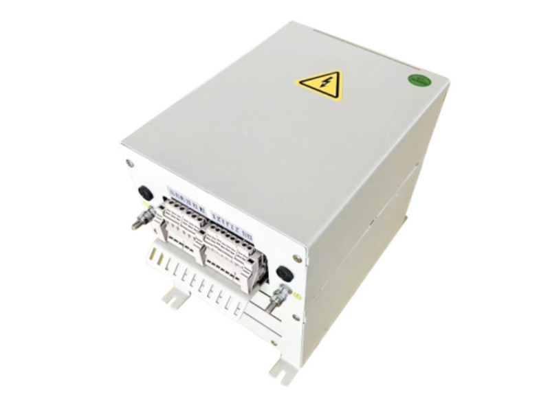
A VFD sine wave filter reduces motor terminal voltage spikes, eliminates PWM harmonics, and extends motor insulation life. Correct selection requires matching carrier frequency, cable length, load impedance, and THD targets to filter LC parameters.
1. What Is a Sine Wave Filter and Why VFD Applications Require One
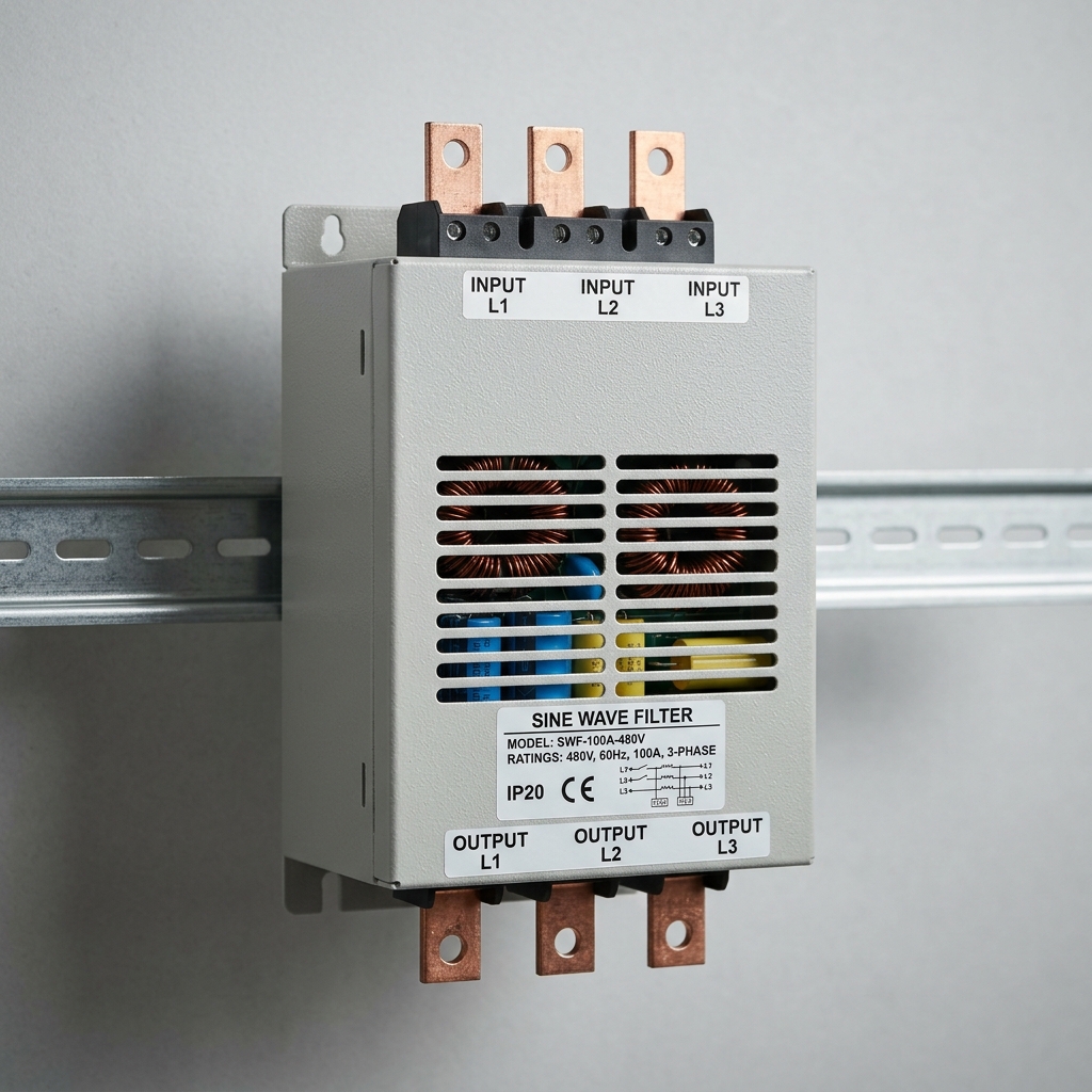
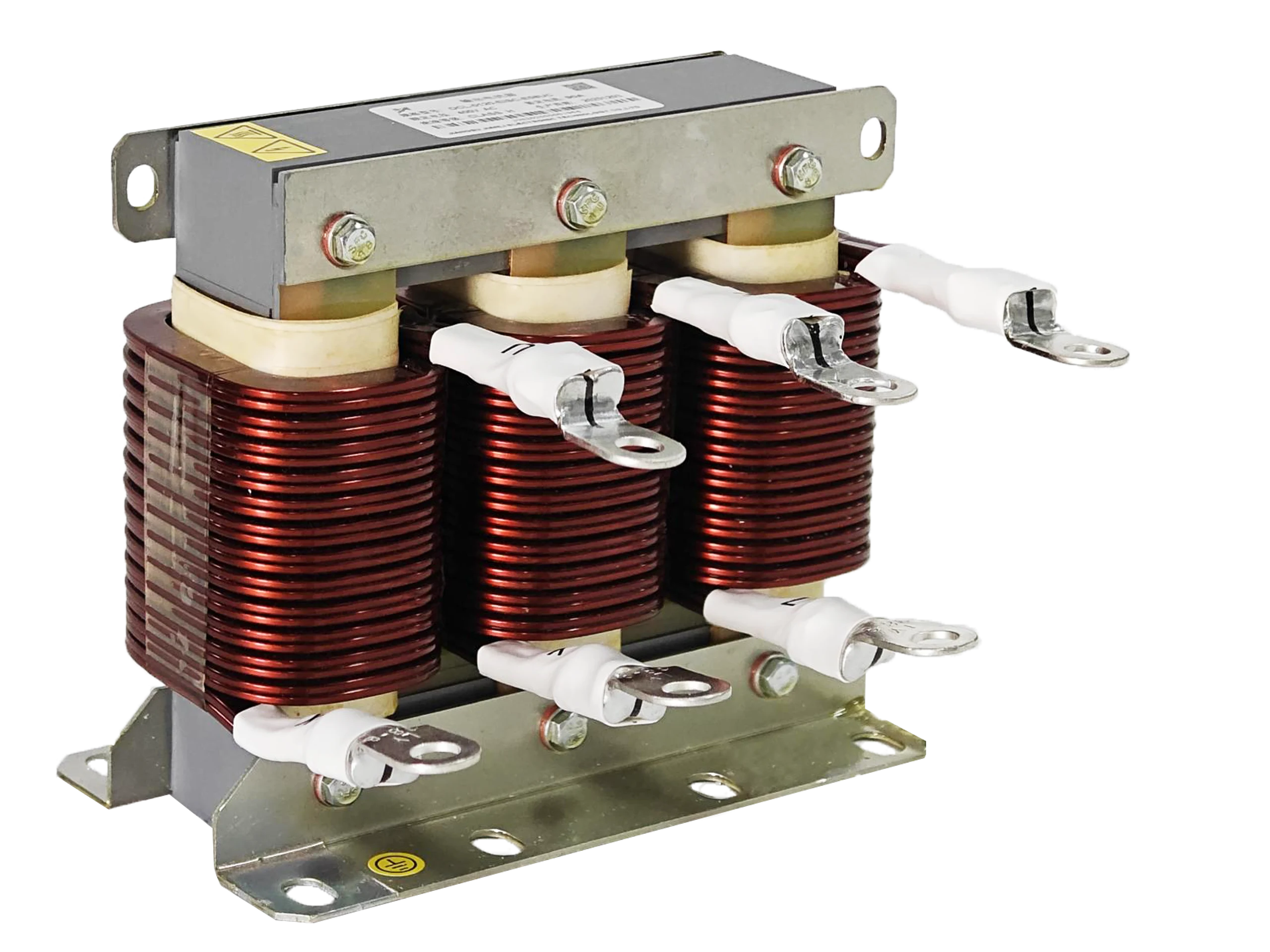
A sine wave filter is an LC low-pass network installed at the VFD output. It converts PWM switching waveforms into near-sinusoidal voltage before the signal reaches the motor terminals.
Core functions:
- Attenuates dV/dt transients (typically >1,000 V/μs from IGBT switching)
- Reduces motor terminal overvoltage caused by cable reflection
- Lowers bearing current and electromagnetic interference (EMI)
- Enables use of standard motors without inverter-duty upgrades
When a sine wave filter is mandatory:
| Condition | Threshold Requiring Filter |
|---|---|
| Motor cable length | >30 m (low-voltage drives) |
| Motor insulation class | Standard IEC Class B/F without inverter rating |
| THD requirement | <5% per IEEE 519-2022 |
| dV/dt at motor terminals | >500 V/μs |
| Acoustic noise sensitivity | High-precision or medical environments |
Without a sine wave filter, reflected wave voltage can reach 2× DC bus voltage (≈1,000 V on a 480 V system), stressing winding insulation and reducing motor MTBF by 30–50%.
2. How Carrier Frequency Affects Sine Wave Filter LC Resonance
The LC resonant frequency of a sine wave filter must be tuned below the VFD carrier frequency to achieve effective attenuation.
Design rule:
- Filter resonant frequency (f_r) = 1 / (2π√LC)
- f_r must be set at 10–20% of carrier frequency for ≥40 dB attenuation
Carrier frequency vs. filter resonance table:
| VFD Carrier Frequency | Recommended f_r Range | Typical L (mH) | Typical C (μF) |
|---|---|---|---|
| 2 kHz | 200–400 Hz | 3.0–5.0 | 20–40 |
| 4 kHz | 400–800 Hz | 1.5–3.0 | 10–20 |
| 8 kHz | 800–1,600 Hz | 0.8–1.5 | 5–10 |
| 16 kHz | 1,600–3,200 Hz | 0.4–0.8 | 2.5–5 |
Critical warnings:
- If f_r is too close to the fundamental (50/60 Hz), the filter introduces voltage drop and phase shift at the operating frequency.
- Mismatched carrier frequency causes filter overheating due to partial harmonic absorption.
- Always verify the VFD’s actual carrier frequency range—many drives allow user adjustment from 2–16 kHz.
Practical implication: When a system integrator changes the carrier frequency for acoustic noise reduction, the existing sine wave filter may fall outside its rated attenuation band. Reselection is required if carrier frequency changes by more than one octave.
3. Cable Length, Reflected Wave, and Motor Insulation Voltage Stress
Cable length is the primary field variable that determines peak voltage stress at motor terminals.
Reflected wave mechanism:
- IGBT switching produces voltage pulses with rise times of 50–200 ns.
- When cable impedance mismatches motor impedance, a reflected wave doubles terminal voltage.
- Critical cable length: L_critical = (rise time × propagation velocity) / 2
Voltage stress vs. cable length (480 V system, 8 kHz carrier):
| Cable Length | Peak Terminal Voltage | Insulation Risk |
|---|---|---|
| <10 m | ~650 V | Low |
| 10–30 m | 650–900 V | Moderate |
| 30–100 m | 900–1,200 V | High |
| >100 m | Up to 1,400 V | Critical |
How the sine wave filter solves this:
- Slows dV/dt to <100 V/μs, eliminating reflected wave conditions
- Reduces peak motor terminal voltage to within 1.1–1.2× supply voltage
- Allows standard motors to operate on long cable runs without rewinding
IEC 60034-17 and NEMA MG1 Part 31 specify maximum dV/dt and peak voltage thresholds for inverter-fed motors. A properly selected VFD output filter ensures compliance with both standards.
4. THD Reduction: Quantifying Sine Wave Filter Effectiveness
Total Harmonic Distortion (THD) is the primary metric for evaluating sine wave filter performance in power quality applications.
THD calculation:
THD(%) = (√(V₂² + V₃² + V₅² + … Vₙ²) / V₁) × 100
Typical THD performance comparison:
| Output Configuration | Voltage THD | Current THD |
|---|---|---|
| VFD without filter | 80–120% | 40–80% |
| VFD + dV/dt filter | 50–70% | 30–50% |
| VFD + sine wave filter | <3–5% | <5–8% |
| Utility grid reference | <1% | <5% |
Measurement standards:
- IEEE 519-2022: Limits voltage THD to 5% at the point of common coupling (PCC)
- IEC 61000-3-2: Governs harmonic current emissions for equipment ≤16 A
- EN 61800-3: Applies to variable-speed drive systems specifically
Key insight: THD reduction quantifies sine wave filter effectiveness by demonstrating that harmonic voltage components above the fundamental are reduced to near-utility levels. This is critical for facilities with sensitive equipment sharing the same bus.
5. Filter Impedance Ratings and VFD Output Derating
Filter impedance directly affects VFD output current capacity and must be factored into system sizing.
Impedance impact on derating:
- Series inductance (L) creates voltage drop: ΔV = I × 2πfL
- At full load (60 Hz, 100 A, 2 mH): ΔV ≈ 75 V (15.6% of 480 V)
- VFD must compensate by boosting output voltage, consuming headroom
Derating guidelines:
| Filter Impedance (% of load impedance) | Required VFD Derating | Voltage Drop at Full Load |
|---|---|---|
| 1–2% | None | <2% |
| 3–5% | 5–10% current derating | 3–5% |
| 5–8% | 10–15% current derating | 5–8% |
| >10% | Not recommended | >10% |
Selection rule: Filter impedance should not exceed 3–5% of the load impedance at rated frequency. Higher impedance requires selecting the next larger VFD frame size.
Capacitor bank effect: The filter’s shunt capacitors draw reactive current continuously. This reactive load appears as additional current on the VFD output, reducing effective active current capacity. Size the VFD at 110–115% of motor FLA when a sine wave filter is installed.
6. Motor Power Factor and Compatibility Under Sine Wave Filtering
A sine wave filter alters the reactive power balance between the VFD and motor, affecting power factor measurement and motor thermal behavior.
Power factor shift mechanism:
- Filter capacitors supply reactive current locally, reducing reactive demand from the VFD
- Displacement power factor (DPF) at VFD output improves from ~0.85 to ~0.95–0.98
- True power factor at motor terminals approaches unity under filtered conditions
Motor compatibility checklist for VFD sine wave filter selection:
- ✅ Standard induction motors (IEC/NEMA): Fully compatible
- ✅ IE3/IE4 premium efficiency motors: Compatible; verify winding insulation
- ✅ Permanent magnet motors: Compatible; confirm no resonance with PM back-EMF
- ⚠️ Synchronous reluctance motors: Check for torque ripple interaction
- ❌ Motors with integral power factor correction capacitors: Incompatible—remove PFC caps before installing filter
Thermal consideration: Improved current waveform quality reduces motor harmonic losses by 15–25%, lowering operating temperature by 5–10°C and extending bearing and winding life.
OEM and system integrator note: When specifying VFD output filter motor compatibility for multi-motor configurations, each motor branch requires individual filter sizing. A single shared filter on a multi-motor bus causes impedance imbalance and unequal load sharing.
7. Practical Application Scenarios
Scenario A: Pump Station with 150 m Cable Run
- Problem: 480 V VFD driving a 75 kW pump; cable length = 150 m; motor insulation failures within 18 months.
- Solution: Installed a sine wave filter (f_r = 600 Hz, matched to 6 kHz carrier); peak terminal voltage reduced from 1,350 V to 530 V; motor MTBF increased 3×.
Scenario B: HVAC System in Hospital Environment
- Problem: PWM harmonics causing interference with medical imaging equipment on shared electrical bus; measured voltage THD = 95%.
- Solution: Sine wave filter reduced voltage THD to 3.8%, complying with IEEE 519-2022; zero interference events post-installation.
Scenario C: Textile Mill Multi-Motor Drive System
- Problem: 12 motors on a common VFD bus; unequal torque distribution due to shared output impedance.
- Solution: Individual sine wave filters per motor branch; current imbalance reduced from 18% to <3%; production waste reduced by 7%.
FAQ: Sine Wave Filter Selection for VFD Systems
Q1: How does carrier frequency affect sine wave filter LC resonance?
Filter resonant frequency must be 10–20% of carrier frequency for effective attenuation.
Q2: How does cable length impact motor insulation voltage stress?
Cables >30 m cause reflected waves doubling terminal voltage to ~1,000–1,400 V on 480 V systems.
Q3: How does THD reduction quantify sine wave filter effectiveness?
Filters reduce voltage THD from 80–120% (unfiltered VFD) to <5%, meeting IEEE 519-2022.
Q4: How do filter impedance ratings affect VFD output derating?
Impedance >5% of load impedance requires 10–15% VFD current derating.
Q5: How does motor power factor change under sine wave filtering?
Filter capacitors improve displacement power factor from ~0.85 to 0.95–0.98 at VFD output.
Q6: What is the minimum carrier frequency for sine wave filter compatibility?
Most sine wave filters require a minimum carrier frequency of 2 kHz for proper harmonic attenuation.
Q7: Can a sine wave filter be used with regenerative VFDs?
Yes, but bidirectional current rating must be verified; standard filters are unidirectional.
Q8: Does a sine wave filter eliminate the need for an EMI filter?
No. Sine wave filters address output harmonics; a separate EMI/RFI filter is required on the input side.
Conclusion and Selection Checklist
Selecting the correct sine wave filter for a VFD requires simultaneous evaluation of five interdependent parameters: carrier frequency alignment, cable length, THD targets, filter impedance derating, and motor compatibility.
Mandatory selection checklist:
- [ ] Confirm VFD carrier frequency range (fixed or adjustable)
- [ ] Measure or estimate motor cable length
- [ ] Identify motor insulation class (standard vs. inverter-duty)
- [ ] Verify applicable THD standard (IEEE 519, IEC 61000, EN 61800)
- [ ] Calculate filter impedance as % of load impedance
- [ ] Derate VFD current capacity by 10–15% if filter impedance >3%
- [ ] Check motor compatibility (remove integral PFC capacitors if present)
- [ ] Validate filter resonant frequency against carrier frequency
Professional recommendation: Engage filter manufacturers with documented test data per IEC 61800-3 and IEEE 519-2022. Request insertion loss curves, dV/dt test reports, and thermal derating data at the system’s specific carrier frequency before finalizing procurement.
References and Standards
- IEEE 519-2022 — Recommended Practice for Harmonic Control in Electric Power Systems
- IEC 61800-3:2017 — Adjustable Speed Electrical Power Drive Systems — EMC Requirements
- IEC 60034-17:2006 — Rotating Electrical Machines — Cage Induction Motors When Fed from Converters
- NEMA MG1-2021, Part 31 — Definite-Purpose Inverter-Fed Polyphase Motors
- IEC 61000-3-2:2018 — Limits for Harmonic Current Emissions
- Mohan, N., Undeland, T.M., Robbins, W.P. — Power Electronics: Converters, Applications, and Design, 3rd Ed., Wiley
- Skibinski, G., Kerkman, R., Schlegel, D. — “EMI Emissions of Modern PWM AC Drives,” IEEE Industry Applications Magazine, 1999