
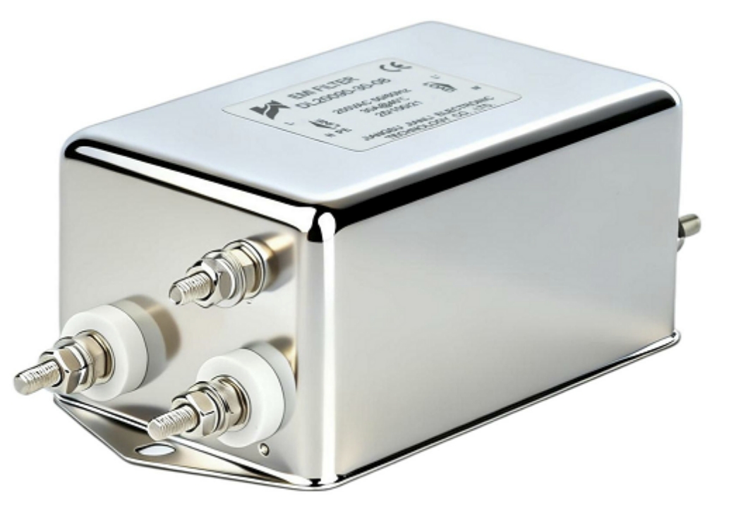
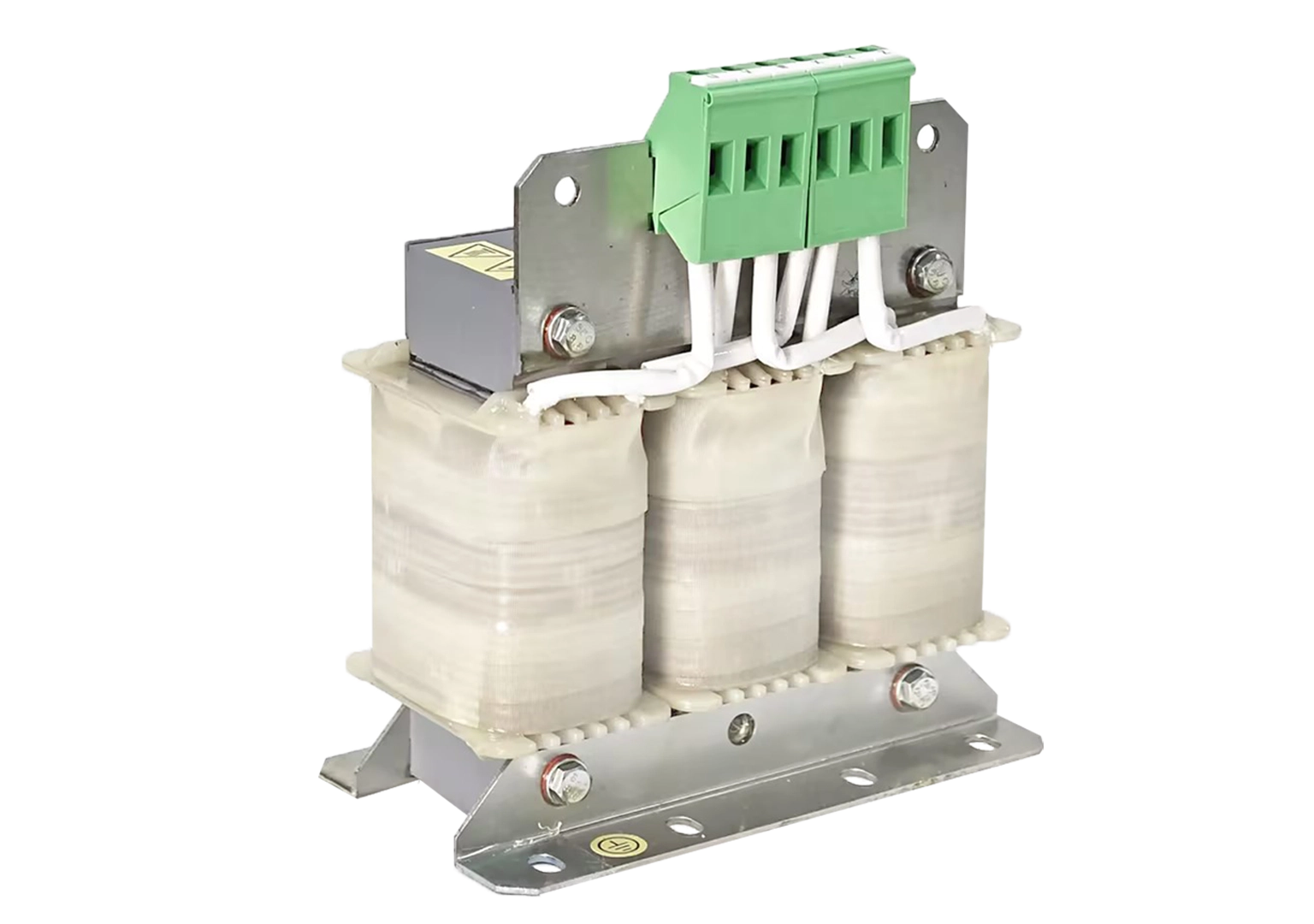
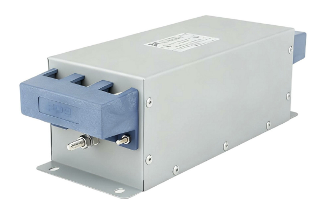
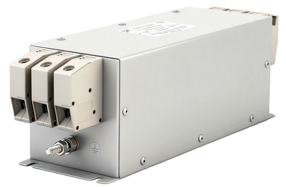
An output reactor is a three-phase inductive filter installed between a VFD and the motor load. It limits dV/dt voltage rise rates, attenuates reflected wave overvoltages on long cable runs, and reduces motor winding insulation stress. Required when cable lengths exceed 30–50 meters or motor insulation class is below inverter-duty rating.
What Is an Output Reactor and How Does It Work
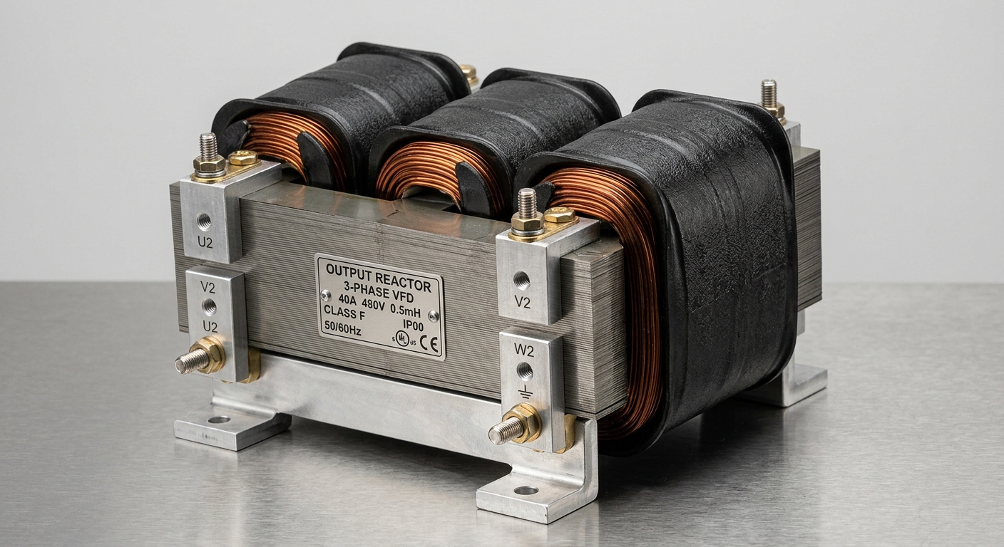
A VFD output reactor is a series-connected three-phase inductor placed at the drive’s output terminals. It operates on fundamental electromagnetic induction principles to condition PWM switching waveforms before they reach motor windings.
Core operating mechanism:
- PWM inverters switch at 2–16 kHz carrier frequencies
- Each switching event generates voltage rise rates (dV/dt) of 5,000–10,000 V/µs
- The reactor’s inductance (typically 2–5% impedance) slows the dV/dt to below 500 V/µs
- Reduced rise rate prevents capacitive coupling between motor winding turns
Key electrical parameters:
| Parameter | Typical Range | Standard Reference |
|---|---|---|
| Impedance (%) | 2% – 5% | IEEE 1312 |
| Inductance | 0.5 mH – 5 mH | IEC 60076-6 |
| dV/dt Reduction | Up to 70% | NEMA MG1 Part 31 |
| Insertion Loss | 0.5% – 1.5% efficiency | IEEE 519 |
The three-phase output reactor presents balanced impedance across all phases, ensuring symmetrical voltage conditioning. Core materials are typically grain-oriented silicon steel (M6 grade) or amorphous alloy, with operating temperatures rated to 130°C (Class B) or 155°C (Class F).
How dV/dt Magnitude Affects Motor Winding Insulation Degradation
This section directly addresses the most critical failure mechanism linking variable frequency drive output reactors to motor longevity.
Degradation pathway:
- High dV/dt creates uneven voltage distribution across winding turns
- Turn-to-turn voltage stress concentrates at first 10–20% of winding
- Partial discharge initiates at voltage stress above 1,000 V/µs on standard motors
- Insulation breakdown follows exponential degradation kinetics
Quantitative insulation stress thresholds:
| Motor Insulation Class | Max Tolerable dV/dt | Peak Voltage Tolerance |
|---|---|---|
| Standard (NEMA Class B) | 500 V/µs | 1,000 V peak |
| Inverter-Duty (NEMA MG1-31) | 2,000 V/µs | 1,600 V peak |
| IEC Form-Wound (Class F) | 1,500 V/µs | 1,800 V peak |
Long cable run amplification:
- Cables exceeding 30 m exhibit transmission line behavior
- Reflected wave phenomenon doubles peak voltage at motor terminals
- At 100 m cable length, terminal voltage can reach 2× DC bus voltage
- 480V drives produce DC bus of ~680V; reflected wave reaches 1,360V peak
Without a VFD output reactor, standard motors on cable runs beyond 50 meters face insulation life reduction from a nominal 20-year design life to under 5 years under continuous PWM stress (per IEEE 1312 accelerated aging models).
Quantitative Selection Criteria for Output Reactors
Proper output reactor selection criteria require matching reactor specifications to system parameters across four variables.
Selection variable 1 — Cable length:
- 0–30 m: Output reactor optional; monitor dV/dt
- 30–100 m: 3% impedance reactor required
- 100–300 m: 5% impedance reactor + dV/dt filter recommended
300 m: Sine wave filter mandatory
Selection variable 2 — Motor voltage rating:
- 230V systems: Reflected wave risk moderate
- 460–480V systems: High risk; reactor required beyond 50 m
- 575–690V systems: Critical risk; reactor required beyond 30 m
Selection variable 3 — Switching frequency:
- Higher carrier frequency (>8 kHz) → higher dV/dt → lower threshold for reactor requirement
- Reduce carrier frequency to 2–4 kHz as alternative mitigation
Selection variable 4 — Motor insulation rating:
- Non-inverter-duty motors: Reactor mandatory with any VFD application
- NEMA MG1 Part 31 motors: Reactor recommended beyond 50 m
- Form-wound HV motors: Reactor always required
Reactor impedance selection table:
| Cable Length | Motor Rating | Recommended Impedance |
|---|---|---|
| <30 m | Inverter-duty | Optional (2%) |
| 30–100 m | Standard | 3% minimum |
| 100–300 m | Any | 5% + dV/dt filter |
| >300 m | Any | Sine wave filter |
Output Reactor Impact on THD and System Power Quality
Industrial VFD output reactor applications extend beyond motor protection to system-level harmonic management.
THD reduction mechanism:
- Output reactors attenuate high-frequency harmonic content in motor current
- Effective against 5th, 7th, and higher-order harmonics generated by PWM modulation
- 3% impedance reactor reduces motor current THD by 15–25% under full load
- THD reduction diminishes at partial load (below 40% rated load)
Insertion loss vs. THD trade-off:
- Every 1% impedance increase reduces efficiency by approximately 0.3–0.5%
- 5% impedance reactor introduces ~1.5% efficiency penalty
- At 100 kW motor load, 1.5% loss = 1.5 kW continuous heat dissipation
- Thermal derating of reactor required at ambient temperatures above 40°C
Variable load performance:
- At 100% load: THD reduction 20–25%, insertion loss 1.2–1.5%
- At 75% load: THD reduction 18–22%, insertion loss 0.9–1.1%
- At 50% load: THD reduction 12–16%, insertion loss 0.6–0.8%
- At 25% load: THD reduction 5–8%, insertion loss 0.3–0.4%
Output reactors do not replace input line reactors or active front-end filters for IEEE 519 compliance at the PCC (Point of Common Coupling). They address load-side harmonics only.
Real-World Application Scenarios
Scenario 1: Pump Station with 150-Meter Cable Run
- System: 75 kW, 480V VFD driving submersible pump
- Problem: Motor winding failures every 18 months; insulation resistance declining
- Solution: 5% impedance three-phase output reactor + reduced carrier frequency (4 kHz)
- Result: dV/dt reduced from 8,500 V/µs to 420 V/µs; motor MTBF extended to 7+ years
Scenario 2: HVAC Chiller Plant — Multiple Motors, Shared Drive Bus
- System: 6× 22 kW motors on common VFD bus, cable lengths 20–80 m
- Problem: Nuisance ground fault trips; EMI interference with building automation
- Solution: Individual 3% output reactors per motor feeder
- Result: Ground fault trips eliminated; EMI emissions reduced by 12 dB
Scenario 3: OEM Conveyor System — Non-Inverter-Duty Motors
- System: Legacy 15 kW motors, 30 m cable, 460V VFD retrofit
- Problem: Motors not rated for inverter duty; replacement cost prohibitive
- Solution: 3% output reactor as interim protection measure
- Result: Extended motor service life by 3–4 years pending scheduled replacement
How Leading VFD Output Reactor Manufacturers Differentiate Specifications
Industrial output reactor products are differentiated across five specification dimensions:
1. Core material technology:
- Silicon steel (standard): Lower cost, suitable for 50/60 Hz base frequencies
- Amorphous alloy cores: 30–40% lower core losses, superior high-frequency performance
2. Thermal class and enclosure:
- Class B (130°C): Standard industrial environments
- Class F (155°C): High-ambient or high-duty-cycle applications
- IP20 / IP54 / IP65 enclosure ratings for environmental protection
3. Certification compliance:
- UL 508A (industrial control panels)
- CE marking (IEC 61000-4 series EMC compliance)
- CSA C22.2 No. 14 (Canadian industrial equipment)
- RoHS compliance for export markets
4. Current rating methodology:
- Continuous rated current (In) vs. peak current (Ipeak)
- Overload capacity: Typically 150% In for 60 seconds
- Derating curves for elevated ambient temperatures
5. Impedance tolerance:
- ±5% impedance tolerance (standard grade)
- ±2% impedance tolerance (precision grade for sensitive applications)
FAQ: Output Reactor Selection for VFD Systems
Q1: At what cable length is an output reactor mandatory for a 480V VFD?
Beyond 50 meters for standard motors; beyond 30 meters for non-inverter-duty motors.
Q2: What impedance percentage optimally limits VFD-induced voltage spikes?
3% impedance for most applications; 5% for cable runs exceeding 100 meters.
Q3: Can an output reactor replace a sine wave filter?
No. Output reactors reduce dV/dt; sine wave filters eliminate PWM harmonics entirely.
Q4: Does an output reactor reduce motor audible noise?
Yes. Attenuating high-frequency harmonics reduces magnetic noise by 3–8 dB typically.
Q5: How does output reactor impedance affect VFD torque response?
5% impedance introduces minor torque response lag; negligible in most pump/fan applications.
Q6: Are output reactors required for inverter-duty motors on short cable runs?
Not required under 30 m; recommended above 30 m regardless of motor insulation rating.
Q7: What is the service life of a properly rated industrial output reactor?
15–25 years under rated conditions; thermal aging is the primary life-limiting mechanism.
Q8: Do output reactors work with all VFD topologies?
Compatible with all standard VSI (Voltage Source Inverter) VFDs; verify compatibility with CSI drives.
Conclusion
An output reactor is a non-optional component in VFD systems where cable runs exceed 50 meters, motor insulation is below inverter-duty rating, or operating voltage is 460V and above. The 3% impedance three-phase output reactor represents the industry-standard solution, reducing dV/dt from typical values of 5,000–10,000 V/µs to below 500 V/µs, extending motor insulation life by a factor of 3–4×, and reducing motor current THD by 15–25% under full-load conditions.
Engineering decision framework:
- Cable > 50 m → specify 3% reactor minimum
- Voltage ≥ 460V + non-inverter-duty motor → specify reactor regardless of cable length
- Cable > 100 m → specify 5% reactor or add dV/dt filter
- Cable > 300 m → replace output reactor with sine wave filter
Consult IEEE 1312, NEMA MG1 Part 31, and IEC 60034-17 for application-specific sizing validation. Source reactors from manufacturers providing UL 508A certification, traceable impedance tolerance data, and thermal derating curves for your installation ambient conditions.
References and Standards
- IEEE Std 1312: Guide for the Application of Power Electronics for Power Quality Improvement
- NEMA MG1 Part 31: Definite Purpose Inverter-Fed Polyphase Motors
- IEC 60034-17: Rotating Electrical Machines — Cage Induction Motors When Fed from Converters
- IEC 60076-6: Power Transformers — Reactors
- IEEE Std 519-2022: Recommended Practice for Harmonic Control in Electric Power Systems
- Mohan, N., Undeland, T.M., Robbins, W.P. (2003). Power Electronics: Converters, Applications, and Design. Wiley.
- Skibinski, G., Kerkman, R., Schlegel, D. (1999). “EMI Emissions of Modern PWM AC Drives.” IEEE Industry Applications Magazine, 5(6), 47–80.