
Abstract
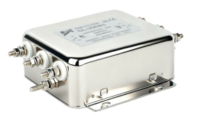
In industrial and commercial power environments, electrical noise is not a minor inconvenience — it is a direct threat to equipment reliability, regulatory compliance, and operational continuity. A three phase filter addresses this threat at the source by suppressing electromagnetic interference (EMI), attenuating harmonic distortion, and stabilizing voltage across all three phases simultaneously.
Modern facilities running variable frequency drives (VFDs), CNC machine tools, servo systems, or large rectifier banks generate significant conducted emissions that propagate back into the power network. Without a properly specified three phase EMI filter, these disturbances degrade sensitive control electronics, trigger nuisance tripping, and create compliance failures under IEC and CISPR standards.
This article provides procurement engineers and system designers with a technically grounded framework for understanding why three phase power line noise filtering is non-negotiable in serious industrial deployments. Topics covered include interference mechanisms, filter topology, key electrical parameters, regulatory requirements, application scenarios, and total cost of ownership — giving decision-makers the information needed to specify the right component with confidence.
1. The Core Problem: What Threatens Three Phase Power Stability?
1.1 Sources of Power Line Noise and Harmonics
Three phase power systems in industrial environments are rarely “clean.” The primary sources of conducted interference fall into two categories:
Common-mode noise appears simultaneously on all phase conductors relative to ground. It is predominantly generated by switching power supplies, inverter outputs, and high-frequency PWM signals from VFDs. Because common-mode currents flow through parasitic capacitances to ground, they are especially difficult to suppress without a dedicated filter topology.
Differential-mode interference exists between phase conductors. Nonlinear loads — including rectifiers, UPS systems, and electronic motor drives — draw current in non-sinusoidal pulses, injecting harmonic distortion (primarily 5th, 7th, 11th, and 13th order harmonics) directly into the supply network. Total harmonic distortion (THD) levels above 5–8% are routinely measured in facilities without adequate filtering.
Switching frequencies from modern power electronics typically range from 4 kHz to 20 kHz, placing the dominant interference squarely within the 150 kHz–30 MHz conducted emissions band regulated by CISPR 11 and CISPR 22.
1.2 Consequences of Unfiltered Power in Industrial Systems
The downstream effects of unaddressed power line noise are commercially significant:
- Premature motor and bearing failure caused by high-frequency shaft voltages induced by common-mode currents
- PLC and HMI data corruption when noise couples into control signal cables sharing conduit with power wiring
- Nuisance tripping of protective relays and circuit breakers responding to distorted waveforms
- EMC non-compliance leading to failed CE or FCC certifications, product recalls, or facility fines
- Reduced capacitor bank lifespan due to harmonic-induced thermal stress
In high-availability environments such as semiconductor fabrication, food processing, or automated warehousing, a single unplanned shutdown can cost tens of thousands of dollars per hour. The three phase power filter is the first and most cost-effective line of defense.
2. How a Three Phase Filter Works: Technical Principles
2.1 Attenuation Mechanism and Filter Topology
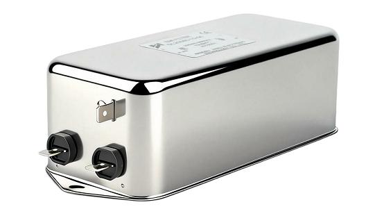
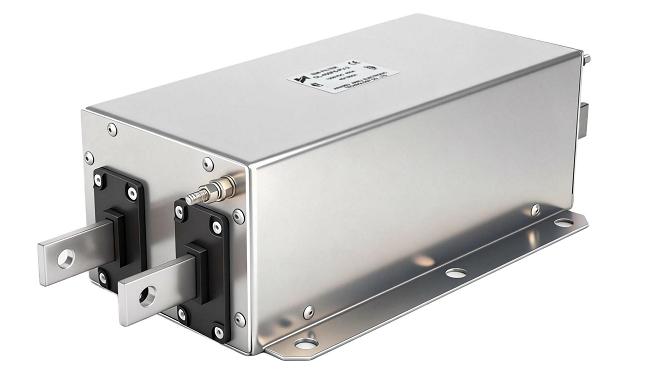
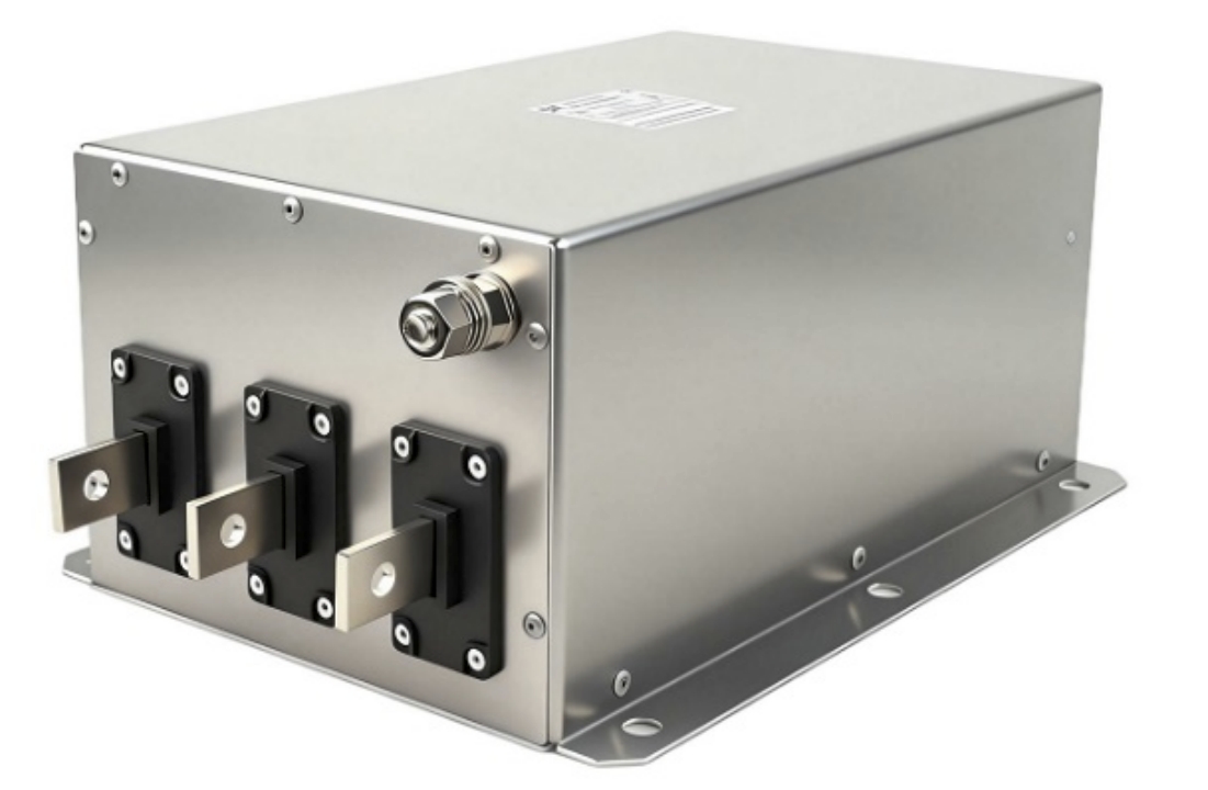
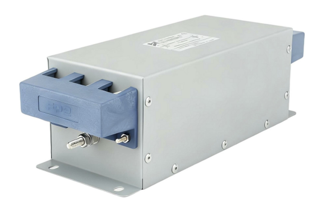
A three phase EMI filter is fundamentally an LC (inductor-capacitor) network inserted between the power source and the load. Its architecture addresses both common-mode and differential-mode interference through complementary components:
- Common-mode choke: A toroidal core wound with all three phase conductors (and neutral, where applicable). Common-mode currents see high impedance and are attenuated; balanced load currents pass through with minimal insertion loss.
- X-capacitors: Connected line-to-line, they form a low-impedance path for differential-mode noise, shunting high-frequency energy before it reaches the load.
- Y-capacitors: Connected line-to-ground, they suppress common-mode noise by providing a controlled return path to the protective earth (PE). Leakage current values are directly determined by Y-capacitor sizing.
- Damping resistors: Included in some designs to prevent resonance peaks that could amplify interference at specific frequencies.
Insertion loss — expressed in dB across a frequency range — is the primary performance metric. A well-designed three phase filter for stable power supply should deliver 40–60 dB of common-mode attenuation and 30–50 dB of differential-mode attenuation across the 150 kHz–30 MHz band.
2.2 Key Electrical Parameters and What They Mean
Selecting the wrong specification is a common and costly procurement error. The table below summarizes the critical parameters procurement engineers must evaluate:
| Parameter | Typical Range | Procurement Significance |
|---|---|---|
| Rated Current (A) | 6A – 2000A | Must exceed maximum continuous load current; apply derating for elevated temperatures |
| Rated Voltage (V) | 250V / 480V / 520V AC | Match to local supply voltage with margin for transient overvoltage |
| Leakage Current (mA) | 0.5 mA – 30 mA | Critical for GFCI-protected circuits and medical-adjacent installations |
| Common-Mode Insertion Loss (dB) | 40 – 80 dB | Higher values required for VFD-intensive environments |
| Differential-Mode Insertion Loss (dB) | 25 – 55 dB | Determines harmonic suppression effectiveness |
| Operating Temperature (°C) | -25°C to +85°C | Verify against enclosure thermal environment |
| Mounting Style | DIN rail/panel mount/chassis mount | Must align with panel layout and installation workflow |
| Certifications | UL, cUL, CE, RoHS | Mandatory for market access and insurance compliance |
| Typical Applications | VFD, CNC, servo, HVAC | Confirms the filter is validated for the intended load type |
Current derating is particularly important: most manufacturers specify a 20–30% derating at ambient temperatures above 40°C. Failure to derate is a leading cause of premature filter failure in enclosed industrial panels.
3. Compliance Standards and Selection Criteria
3.1 EMC Regulatory Requirements for Three Phase Filters
Regulatory compliance is not optional in any market served by CE marking, UL listing, or equivalent national frameworks. The key standards governing three phase EMI filter performance include:
- IEC/EN 61000-4-x series: Defines immunity requirements for conducted and radiated disturbances, surge, and EFT (electrical fast transient) events
- CISPR 11 (industrial, scientific, medical equipment) and CISPR 22 (IT equipment): Set conducted emission limits in the 150 kHz–30 MHz band; Class A limits apply to industrial environments
- EN 55011 / EN 55032: European harmonized emission standards for industrial machinery and multimedia equipment
- UL 1283: North American standard for electromagnetic interference filters, required for UL-listed panel assemblies
A three phase filter bearing both CE and UL/cUL marks provides the broadest market coverage and simplifies compliance documentation for OEMs exporting to multiple regions.
3.2 How to Select the Right Three Phase EMI Filter
Beyond electrical parameters, installation and application context drive selection:
Load type matching: VFDs and servo drives generate predominantly high-frequency common-mode noise and require filters with high common-mode inductance. Rectifier-based loads produce low-order harmonics that demand stronger differential-mode attenuation.
Derating for environment: In panels where ambient temperature exceeds 40°C or airflow is restricted, select the next higher current rating. For outdoor or harsh-environment installations, verify IP54 or IP65 enclosure ratings.
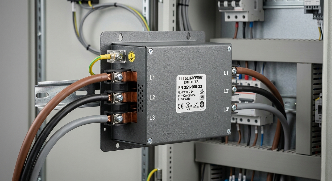
Cable routing: A three phase power filter delivers its rated performance only when input and output cables are physically separated. Routing them in parallel over long distances couples noise back across the filter, negating attenuation. Keep input/output separation at minimum 10 cm or use shielded conduit.
Leakage current constraints: In facilities with sensitive GFCI protection or where personnel safety regulations impose strict earth leakage limits, specify low-leakage variants (typically ≤1 mA per phase).
4. Application Scenarios and Commercial Value
4.1 Typical Industrial and Commercial Use Cases
The three phase filter for stable power supply is deployed across a wide range of demanding environments:
- VFD and servo drive systems: The single largest application. Filters prevent drive-generated EMI from propagating upstream and protect encoder feedback signals from noise coupling.
- CNC machine tools: High-precision positioning systems are acutely sensitive to power line noise; even sub-microsecond voltage spikes can cause positioning errors or axis faults.
- Industrial automation panels: PLCs, distributed I/O, and HMI systems require clean power rails; a three phase filter at the panel inlet protects all downstream devices collectively.
- Renewable energy inverters: Grid-tied solar and wind inverters must meet strict conducted emission limits; three phase EMI filters are integral to inverter CE certification.
- Commercial HVAC and chiller systems: Large compressor drives and soft starters benefit from upstream filtering to protect building management system (BMS) communications.
- Data center PDUs: Three phase distribution in hyperscale and colocation facilities requires filtering to maintain power quality for sensitive server loads.
4.2 ROI and System-Level Benefits for Procurement Decision-Makers
The commercial case for specifying a certified three phase EMI filter is straightforward when evaluated against total cost of ownership:
- Reduced unplanned downtime: A single prevented shutdown in a manufacturing line typically recovers the filter’s cost 10–50× over
- Extended equipment lifespan: Motors, drives, and capacitor banks operating on filtered power demonstrate measurably lower failure rates — industry data consistently shows 20–40% longer MTBF in filtered installations
- Warranty and insurance protection: Many drive manufacturers require upstream EMI filtering to maintain warranty validity; insurers increasingly require documented EMC compliance
- Simplified certification: Integrating a pre-certified three phase filter reduces the EMC testing burden for OEM machine builders, accelerating time-to-market
- Scalable architecture: Modular filter designs allow current rating upgrades without rewiring, protecting the capital investment as production capacity grows
FAQ
Q1: What is the difference between a three phase EMI filter and a standard power line noise filter for three phase systems?
The terms are often used interchangeably, but “EMI filter” specifically implies a component designed and tested to meet conducted emission limits per CISPR or equivalent standards, with documented insertion loss curves. A generic “power line noise filter” may lack third-party certification or published attenuation data. For compliance-critical applications, always specify a certified three phase EMI filter with traceable test reports.
Q2: How do I determine the correct current rating when selecting a three phase filter for a variable frequency drive?
Use the drive’s input current rating (not motor nameplate current) as the baseline. Apply a minimum 1.25× safety factor, then apply temperature derating if panel ambient exceeds 40°C. For example, a 30A drive in a 50°C enclosure may require a 50A-rated filter after derating.
Q3: Does installing a three phase power filter affect system efficiency or introduce voltage drop under full load?
A properly designed filter introduces less than 1–2V voltage drop at rated current — negligible in 400V or 480V systems. Power loss is typically 0.1–0.3% of rated load, well within acceptable efficiency budgets. The efficiency trade-off is far outweighed by the protection and compliance benefits delivered.
Conclusion
A three phase filter is not an optional accessory added at the end of a project — it is a foundational infrastructure component that determines whether a power system is stable, compliant, and commercially defensible. From suppressing VFD-generated common-mode noise to enabling CE and UL certification, the three phase EMI filter delivers measurable value at every level: electrical, regulatory, and financial.
Procurement engineers who specify certified three phase power line noise filters as standard practice reduce warranty exposure, protect equipment investments, and build systems that perform reliably across their full operational lifespan. In an era where unplanned downtime carries escalating costs and EMC regulations grow more stringent annually, the question is no longer whether to use a three phase filter — it is which specification best fits the application.