
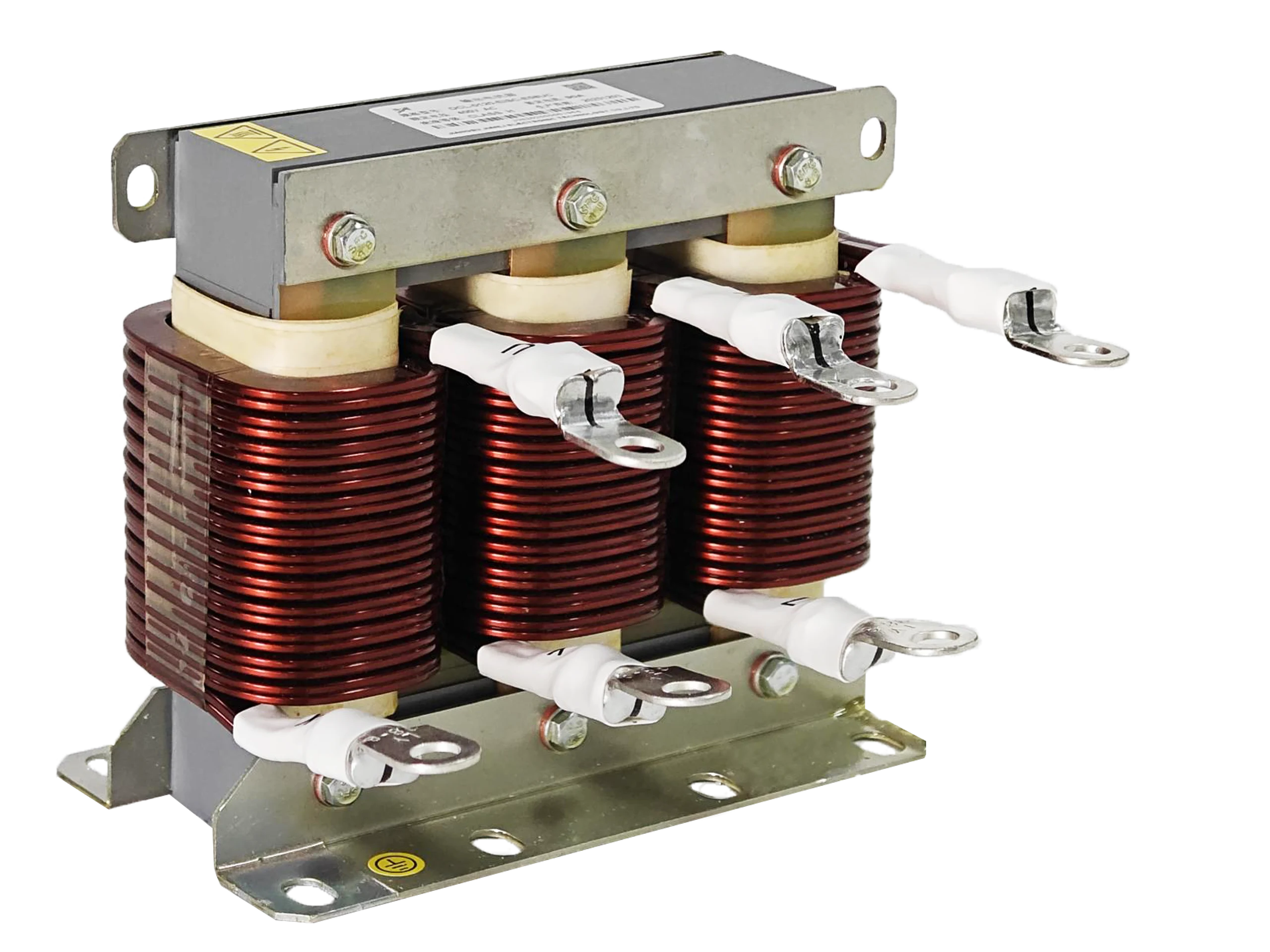
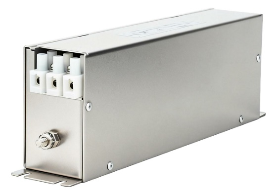
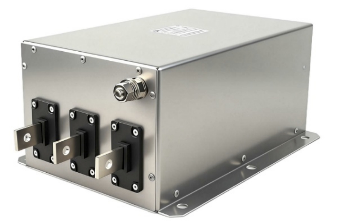
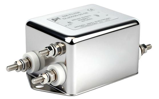
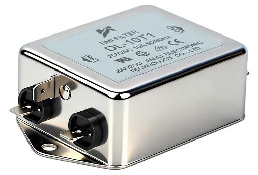
Three phase EMI filter performance is constrained by four interdependent factors: impedance mismatch, noise mode separation, leakage current limits, and installation quality. Optimizing all four simultaneously determines real-world attenuation effectiveness.
1. Insertion Loss Fundamentals and Impedance Mismatch
What Insertion Loss Actually Measures
Insertion loss (IL) quantifies attenuation in decibels between an unfiltered and filtered circuit. Standard IEC 60939-3 defines IL measurement under 50Ω/50Ω source-load conditions—a controlled lab environment rarely replicated in industrial deployments.
- IL is frequency-dependent: typically 10–20 dB at 150 kHz, rising to 40–60 dB at 30 MHz
- Rated IL values apply only at the impedance conditions specified on the datasheet
- Real industrial source impedance ranges from 0.1Ω to over 100Ω depending on transformer rating and cable length
How Source Impedance Mismatch Degrades Performance
Source impedance mismatch is the single largest cause of field performance deviation from datasheet specifications.
- A filter designed for 50Ω source performs 15–25 dB below rated IL when source impedance drops to 1Ω
- Low-impedance sources (large transformers, short busbars) reduce the voltage division ratio across filter inductors
- High-impedance sources cause capacitive filter elements to load the circuit, generating resonance peaks at 2–10 kHz
- Resonance peaks can amplify noise by 6–12 dB at specific frequencies, worsening EMC compliance
Mitigation: Select filters with impedance-matched LC networks. Request IL curves measured at actual source impedance from the three phase EMI filter manufacturer.
| Source Impedance | IL Deviation from 50Ω Rated | Risk Level |
|---|---|---|
| 50Ω (standard) | 0 dB | Baseline |
| 10Ω | −8 to −12 dB | Moderate |
| 1Ω | −15 to −25 dB | High |
| 0.1Ω | −25 to −40 dB | Critical |
2. Common-Mode vs. Differential-Mode Noise in Three-Phase Systems
Noise Generation Mechanisms in VFDs
Variable frequency drives (VFDs) generate both noise types simultaneously through distinct physical mechanisms.
Common-mode (CM) noise:
- Generated by parasitic capacitance between IGBT switching nodes and motor frame ground
- Switching frequencies of 4–16 kHz create CM voltage transients of 500V–2000V peak
- CM current flows through all three phases simultaneously, returning via ground conductor
- Frequency range: 150 kHz–30 MHz (conducted), extending to 1 GHz (radiated)
Differential-mode (DM) noise:
- Generated by pulsed DC bus ripple and asymmetric switching between phase pairs
- Appears as voltage difference between individual phase conductors
- Dominant frequency range: 150 kHz–1 MHz in most VFD topologies
- Amplitude typically 20–40 dB lower than CM noise in three-phase PWM drives
Filter Topology for Each Mode
| Noise Type | Filter Element | Typical Component Values | Attenuation Target |
|---|---|---|---|
| Common-mode | CM choke (toroidal core) | 1–10 mH inductance | 40–60 dB |
| Common-mode | Y-capacitors (line-to-ground) | 4.7–47 nF per phase | 20–30 dB |
| Differential-mode | DM inductor (leakage inductance) | 50–500 µH | 30–50 dB |
| Differential-mode | X-capacitors (line-to-line) | 0.1–4.7 µF | 20–40 dB |
Most three phase EMI filter designs integrate CM chokes with controlled leakage inductance to address both modes within a single housing. The DM suppression relies on the choke’s leakage inductance plus dedicated X-capacitors, while CM suppression depends on the magnetizing inductance and Y-capacitor values.
3. Leakage Current Constraints in Industrial Deployment
Why Leakage Current Limits Filter Design
Y-capacitors connecting line conductors to protective earth (PE) are the primary CM noise suppression element—but they also create leakage current at power frequency (50/60 Hz).
- Leakage current = V_line × 2πf × C_Y (per phase)
- A 47 nF Y-capacitor on a 400V/50Hz system produces approximately 5.9 mA leakage per phase
- Three-phase systems with three Y-capacitors per phase can generate 50–100 mA total leakage
Regulatory Thresholds by Application
| Application Standard | Max Leakage Current | Y-Capacitor Limit (400V/50Hz) |
|---|---|---|
| IEC 60950-1 (IT equipment) | 3.5 mA | ~11 nF per phase |
| IEC 60335 (household appliances) | 0.75 mA | ~2.4 nF per phase |
| IEC 61800-3 (VFD systems) | 100 mA (with PE) | ~33 nF per phase |
| EN 60939 industrial (PE bonded) | 30–300 mA | Application-defined |
Critical deployment constraint: In TN-S and TT grounding systems, leakage current above 30 mA triggers RCD (residual current device) tripping. Industrial sites with multiple VFDs and three phase EMI filters must calculate cumulative leakage across all connected equipment.
- Each 10 nF of Y-capacitance contributes ~1.26 mA at 400V/50Hz
- Systems with 10+ drives can accumulate 500 mA+ total leakage, requiring RCD bypass or type-B RCDs
- Three phase EMI filter leakage current specifications must be verified against site grounding topology before procurement
4. Installation Errors That Destroy Attenuation Performance
The Five Most Damaging Installation Mistakes
Poor installation negates filter design performance more frequently than component selection errors. EMC test failures traced to installation account for over 60% of field compliance issues (based on IEC 61800-3 audit data).
1. Bypassing the filter with long input/output cables routed together
- Capacitive coupling between unfiltered input and filtered output cables re-introduces noise
- Minimum separation: 200 mm between input and output cable runs
- Shielded conduit on output side reduces coupling by 20–40 dB
2. Poor PE bonding at filter chassis
- PE bond impedance above 10 mΩ reduces CM current return path effectiveness
- Use short, wide copper straps (≤50 mm length, ≥25 mm² cross-section)
- Star-point grounding at filter enclosure eliminates ground loop interference
3. Excessive cable length between filter and VFD
- Each additional meter of cable adds 10–15 nH/m inductance in series with filter output
- Recommended maximum: 300 mm between filter output terminals and VFD input
- Long cables create resonant circuits with filter capacitors, producing IL peaks
4. Installing filter after the main circuit breaker with long unfiltered leads
- Unfiltered leads act as antennas, radiating conducted noise before attenuation
- Filter must be positioned at the panel entry point, not downstream
5. Incorrect phase orientation with asymmetric CM chokes
- Reversed phase wiring in wound CM chokes cancels magnetic flux, reducing CM inductance by 80–95%
- Always verify phase rotation matches choke winding direction per manufacturer datasheet
5. Technical Specifications That Differentiate Three Phase EMI Filter Suppliers
Core Datasheet Parameters to Evaluate
When qualifying a three phase EMI filter supplier, datasheet completeness directly indicates engineering rigor.
Mandatory specifications for industrial procurement:
- IL curves measured at multiple impedance conditions (0.1Ω, 1Ω, 50Ω, 100Ω), not just 50Ω/50Ω
- Separate CM and DM insertion loss plots across 150 kHz–30 MHz
- Leakage current measured at rated voltage and frequency (not estimated)
- Operating temperature range with derating curves (typically −25°C to +85°C)
- Rated current at 40°C ambient with thermal resistance data
- Dielectric withstand voltage: minimum 2500 VAC for 1 minute per IEC 60939
- Conducted emissions compliance: CISPR 11 Class A or Class B, EN 55011
Supplier Qualification Checklist
| Parameter | Minimum Acceptable | High-Performance Target |
|---|---|---|
| IL at 1 MHz (50Ω/50Ω) | 40 dB | 60 dB |
| CM inductance | 1 mH | 5–10 mH |
| Leakage current (400V/50Hz) | <30 mA | <10 mA |
| Operating current accuracy | ±10% of rated | ±5% with derating |
| Certifications | CE, RoHS | UL, TÜV, CE, RoHS, REACH |
| IL measurement standard | IEC 60939-3 | IEC 60939-3 + real impedance |
Three phase EMI filter specifications must align with the specific VFD switching frequency, cable topology, and site grounding system—not generic catalog values.
6. Real-World Application Scenarios
Scenario 1: 75 kW VFD in Automotive Manufacturing
- Problem: CISPR 11 Class A failure at 2 MHz on conducted emissions scan
- Root cause: CM noise from 8 kHz IGBT switching, 15 mA leakage causing nuisance RCD trips
- Solution: 75A three phase EMI filter with 4.7 mH CM inductance, Y-caps reduced to 22 nF/phase; PE strap shortened to 40 mm
- Result: 18 dB margin below Class A limit; leakage reduced to 8.3 mA
Scenario 2: 200 kW Pump Station with Multiple Drives
- Problem: Cumulative leakage of 380 mA from eight VFDs tripping 300 mA RCD
- Root cause: Each filter specified at 47 nF Y-caps; cumulative leakage not calculated at system level
- Solution: Replaced with low-leakage three phase EMI filter variants (10 nF Y-caps); installed Type-B RCD rated 500 mA
- Result: Cumulative leakage reduced to 81 mA; full CISPR 11 Class A compliance retained
Scenario 3: CNC Machining Center EMC Certification
- Problem: Radiated emissions failure at 150 MHz attributed to unfiltered motor cable acting as antenna
- Root cause: Filter installed 800 mm from VFD with unshielded cable; IL degraded by 22 dB at 150 MHz
- Solution: Filter repositioned to within 250 mm of VFD; shielded cable with 360° termination added
- Result: 14 dB margin below EN 55011 Class A radiated limit achieved
FAQ: Three Phase EMI Filter — Rapid Technical Reference
Q: How does source impedance mismatch degrade insertion loss performance?
Low source impedance reduces voltage division across filter inductors, cutting real IL by 15–25 dB versus rated values.
Q: What leakage current thresholds limit industrial three-phase filter deployment?
IEC 61800-3 permits 100 mA per drive; RCD protection typically limits site-wide cumulative leakage to 30–300 mA.
Q: How do common-mode and differential-mode noise mechanisms differ in VFDs?
CM noise flows through all phases to ground via parasitic capacitance; DM noise appears as voltage difference between phase pairs.
Q: Which installation errors most severely reduce three-phase EMI filter attenuation?
Routing input/output cables together and poor PE bonding are the two highest-impact errors, degrading IL by 20–40 dB.
Q: What specifications differentiate qualified three-phase EMI filter suppliers technically?
IL curves at multiple impedance conditions, separate CM/DM plots, and verified leakage current at rated voltage are the key differentiators.
Q: What is the typical insertion loss range for a three phase EMI filter at 1 MHz?
40–60 dB under standard 50Ω/50Ω conditions; 20–45 dB under real industrial impedance conditions.
Q: Can one filter design address both CM and DM noise in a VFD system?
Yes. Integrated designs use CM choke leakage inductance for DM suppression and magnetizing inductance plus Y-caps for CM suppression.
Q: How does operating temperature affect three phase EMI filter performance?
Core permeability decreases above 85°C, reducing CM inductance by 15–30%; current derating of 2–3% per °C above 40°C is standard.
Conclusion
Three phase EMI filter performance in industrial power systems is governed by four measurable, controllable parameters: insertion loss under real impedance conditions, balanced CM and DM attenuation topology, leakage current compliance with site grounding architecture, and installation precision.
Key engineering takeaways:
- Always request IL data at source impedance matching your actual system, not standard 50Ω lab conditions
- Calculate cumulative leakage current across all drives before specifying Y-capacitor values
- Separate CM and DM noise paths require distinct filter elements; integrated designs must specify both independently
- Installation quality—PE bonding, cable separation, filter placement—determines whether rated performance is achieved in the field
- Supplier qualification must include IEC 60939-3 test data, real-impedance IL curves, and application-specific derating information
For procurement teams and EMC engineers evaluating three phase EMI filter manufacturers, the differentiating factor is not catalog current rating—it is the depth of application-specific technical data provided to support system-level compliance engineering.
References and Standards
- IEC 60939-3: Passive Filter Units for Electromagnetic Interference Suppression — Sectional Specification
- IEC 61800-3: Adjustable Speed Electrical Power Drive Systems — EMC Requirements
- CISPR 11 / EN 55011: Industrial, Scientific and Medical Equipment — Radio-Frequency Disturbance Characteristics
- IEC 60050-161: International Electrotechnical Vocabulary — Electromagnetic Compatibility
- IEC 61000-4-6: Electromagnetic Compatibility — Immunity to Conducted Disturbances
- MIL-STD-461G: Requirements for the Control of Electromagnetic Interference Characteristics
- Nave, R. (2023). EMI Filter Design, Third Edition. CRC Press.
- Williams, T. (2021). EMC for Product Designers, Fifth Edition. Newnes/Elsevier.