
Abstract
Conducted electromagnetic interference (EMI) remains one of the most persistent challenges in modern power electronics. Switching power supplies, variable frequency drives, EV chargers, and industrial control systems all generate high-frequency noise that propagates back through AC power lines—potentially disrupting sensitive downstream equipment and triggering regulatory non-compliance.
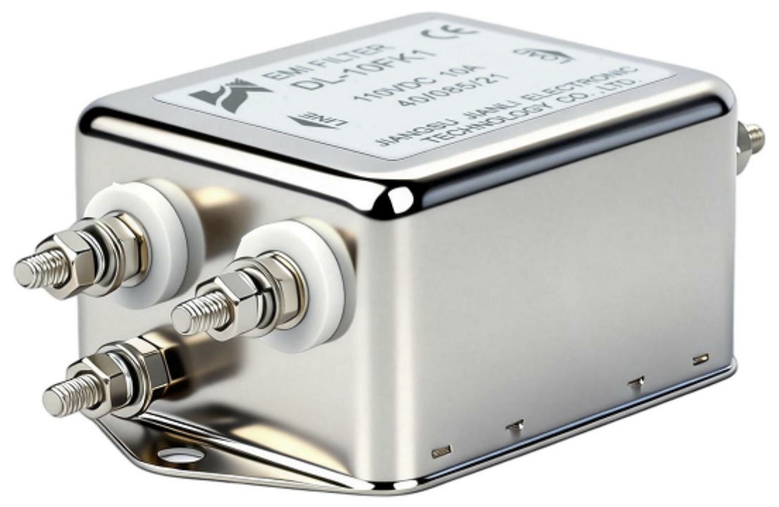
A single phase EMI filter is the first line of defense against this problem. By integrating passive filtering networks directly into the power entry path, these components attenuate both common-mode and differential-mode noise across the 150 kHz to 30 MHz frequency range mandated by international EMC standards.
This article is written for procurement engineers, system integrators, and OEM designers who need to understand how single-phase EMI filters work, what specifications drive performance, and how to select the right component to reduce conducted EMI while supporting product certification timelines. We will cover filter topology, insertion loss performance, selection criteria, and real-world application scenarios.
1. What Is Conducted EMI and Why It Matters in Single-Phase Systems
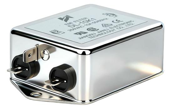
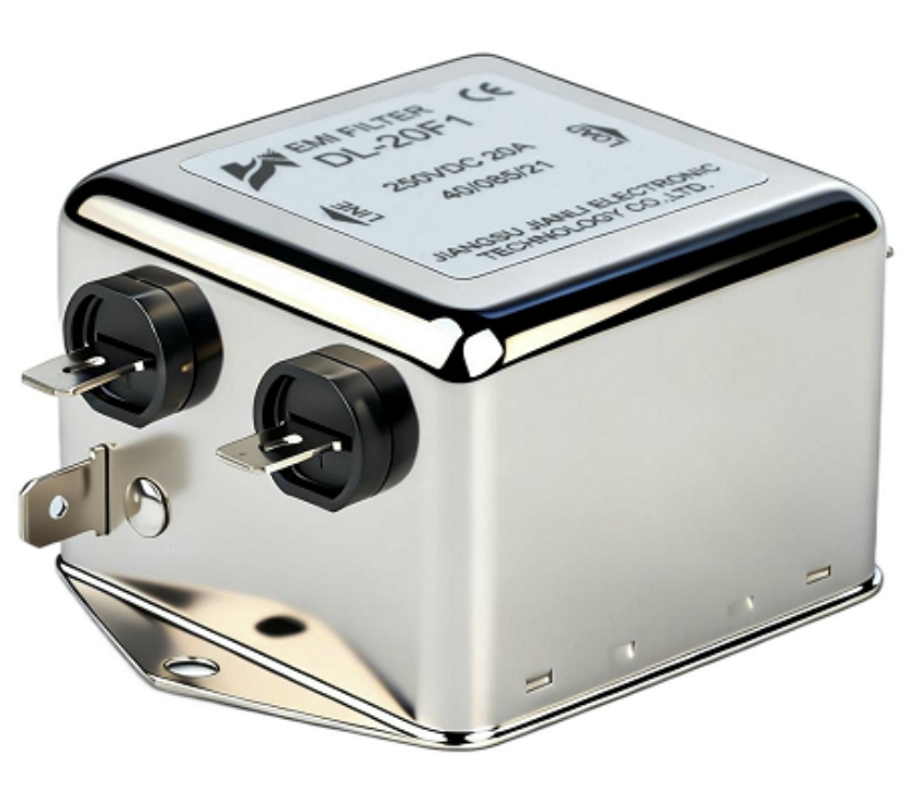
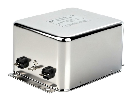
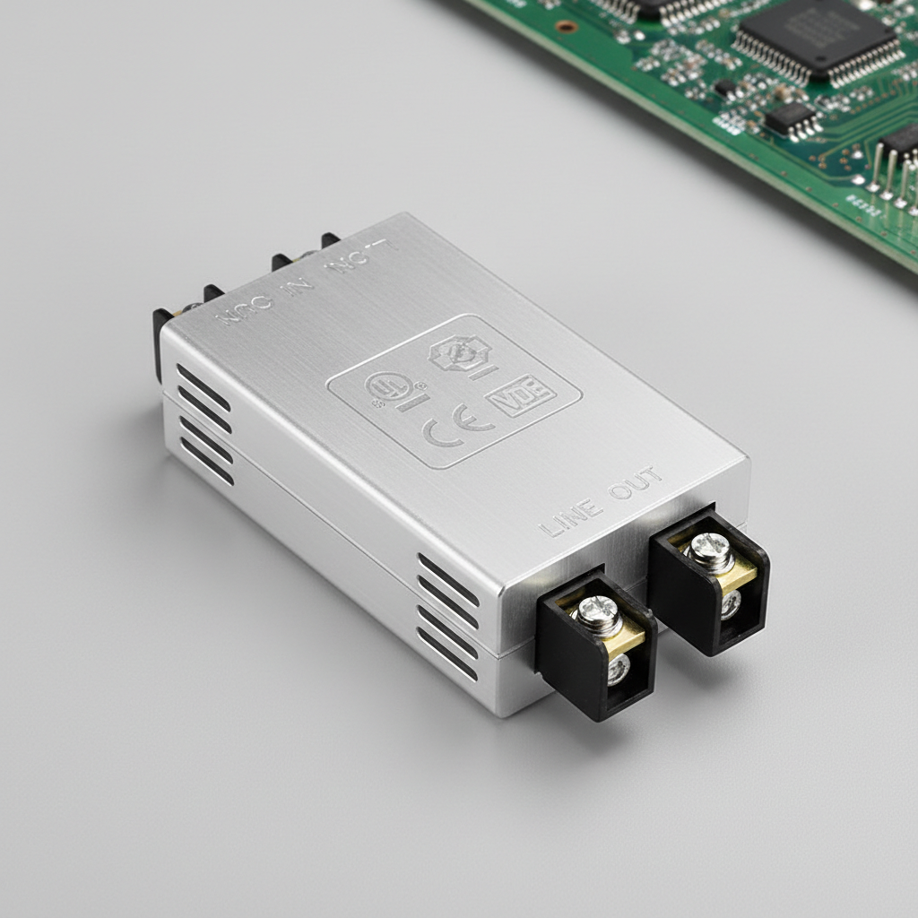
Here is your high-fidelity, photorealistic B2B industrial image of a single phase EMI filter component, ready for a professional product catalog:
1.1 Common-Mode vs. Differential-Mode Noise
Conducted EMI in single-phase AC systems travels in two fundamentally different modes, each requiring a distinct suppression strategy.
Common-mode (CM) noise flows in the same direction on both the live (L) and neutral (N) conductors, returning via the protective earth (PE) ground. It is primarily generated by parasitic capacitances between switching transistors and chassis ground in power converters. CM noise is particularly hazardous in sensitive medical and instrumentation equipment because it couples into signal ground references, causing measurement errors or system faults.
Differential-mode (DM) noise flows in opposite directions on L and N—essentially riding on top of the 50/60 Hz supply voltage. Switching current ripple from inductors and capacitors in SMPS designs is the dominant DM noise source. DM noise directly distorts the supply waveform and can cause logic errors, data corruption, or tripping of over-current protection.
Understanding both propagation paths is essential because a filter optimized only for CM suppression will leave DM noise largely unattenuated—and vice versa. Effective single-phase EMI filters address both simultaneously through a carefully balanced passive network.
1.2 Regulatory Drivers: EMC Standards for Electronic Equipment
Regulatory pressure is a primary commercial driver for EMI filter adoption. Key standards include:
- CISPR 32 / EN 55032: Sets conducted emission limits (Class A and Class B) for multimedia equipment from 150 kHz to 30 MHz.
- IEC 61000-3-2: Governs harmonic current emissions for equipment with input current ≤16 A per phase.
- FCC Part 15 Subpart B: Mandates conducted emission limits for unintentional radiators sold in the US market (Class A: commercial; Class B: residential).
- IEC 60601-1-2: Applies stricter EMC requirements to medical electrical equipment, including tighter leakage current thresholds.
Non-compliance carries real commercial consequences: product recalls, delayed market entry, and reputational damage. Integrating a properly rated single phase EMI filter during the design phase—rather than as a retrofit—dramatically reduces the risk of failing conducted emissions tests.
2. How a Single Phase EMI Filter Suppresses Conducted EMI
2.1 Core Topology and Component Architecture
A standard single-phase EMI filter combines four passive component types in a balanced ladder network:
- X-capacitors (connected line-to-line, L–N): Shunt differential-mode noise to the opposite conductor. Rated for continuous AC voltage, typically Class X2 (250 VAC) or X1 (440 VAC).
- Y-capacitors (connected line-to-ground, L–PE and N–PE): Shunt common-mode noise to protective earth. Class Y2 capacitors are standard for 250 VAC applications; Y1 for double-insulated designs. Y-capacitor values are tightly constrained by leakage current limits.
- Common-mode choke (CMC): A toroidal inductor wound with bifilar windings on a high-permeability ferrite core. Both L and N conductors pass through the same core in opposing directions—DM currents cancel magnetically, while CM currents see high impedance. Typical CM inductance: 1 mH to 47 mH.
- Differential-mode inductors: Either discrete DM chokes or the leakage inductance of the CMC itself provides additional DM attenuation at higher frequencies.
This topology creates a two-stage LC network that progressively attenuates noise from the equipment side before it reaches the mains, and vice versa. The physical arrangement—typically in a shielded metal housing with separated input/output terminals—prevents capacitive coupling that would degrade high-frequency performance.
2.2 Insertion Loss Performance and Frequency Response
Insertion loss (IL) is the primary performance metric, defined as the ratio (in dB) of the voltage appearing at the load without the filter to the voltage with the filter installed, measured under 50 Ω/50 Ω source-impedance conditions per CISPR 17.
Effective single-phase EMI filters deliver:
- CM insertion loss: 40–80 dB across 150 kHz–30 MHz
- DM insertion loss: 30–60 dB across 150 kHz–30 MHz
Key design variables affecting insertion loss include:
- CMC inductance and core material: Nanocrystalline cores offer superior permeability at high frequencies compared to standard ferrite, extending effective attenuation bandwidth.
- Y-capacitor value: Higher capacitance improves CM attenuation but increases leakage current—a critical tradeoff for medical applications.
- Component layout and shielding: Parasitic coupling between input and output traces is the dominant failure mode at frequencies above 10 MHz.
Single Phase EMI Filter — Typical Parameter Comparison
| Parameter | Standard Grade | High-Performance Grade |
|---|---|---|
| Rated Voltage (VAC) | 250 VAC | 250–480 VAC |
| Rated Current (A) | 1–30 A | 1–100 A |
| Leakage Current (mA) | ≤3.5 mA | ≤0.5 mA (medical) |
| CM Insertion Loss @ 1 MHz | ≥40 dB | ≥60 dB |
| DM Insertion Loss @ 1 MHz | ≥30 dB | ≥50 dB |
| Operating Temperature (°C) | −25 to +85 | −40 to +100 |
| Certifications | CE, UL | UL 1283, VDE, CQC, CB |
| Typical Application | Industrial drives, SMPS | Medical PSU, EV charger |
3. Key Specifications and Selection Criteria for Procurement
3.1 Electrical and Mechanical Ratings
Current rating is the most critical electrical parameter. Procurement engineers must account for:
- Derating curves: Most filter manufacturers specify a derating factor at elevated temperatures (typically 20–30% derating at 85°C ambient). Operating a 10 A filter at its nameplate rating in a 70°C enclosure without derating will accelerate core saturation and capacitor aging.
- Inrush current tolerance: Equipment with large bulk capacitors generates high inrush at power-on. Verify the filter’s peak current rating exceeds the expected inrush.
Mechanical form factor directly impacts integration complexity:
- PCB-mount filters: Compact, cost-effective for consumer electronics and low-current (≤6 A) designs. Limited thermal dissipation.
- Panel-mount / IEC inlet filters: Combine EMI filtering with the power entry connector. Ideal for industrial enclosures and appliances.
- DIN rail mount: Preferred for control cabinet integration in industrial automation, offering tool-free installation and easy field replacement.
Terminal type (screw, quick-connect, solder pin) should align with the assembly process to avoid introducing high-resistance connections that degrade filter performance.
3.2 Compliance Certifications and Safety Standards
Certification requirements vary by market and application:
- UL 1283 (North America): Covers EMI filters for use in information technology and industrial equipment. Mandatory for UL-listed end products sold in the US.
- IEC 60939 / EN 60939: The primary international standard for passive EMC components. Required for CE marking in the European market.
- VDE certification: German market preference; widely recognized as a high-confidence safety benchmark globally.
- CQC (China): Required for products entering the Chinese domestic market under CCC certification schemes.
Leakage current is a non-negotiable differentiator for medical applications. IEC 60601-1 limits earth leakage to 500 µA for patient-contact equipment—far below the 3.5 mA permitted in industrial contexts. This constraint forces medical-grade filter designers to use smaller Y-capacitors, which in turn requires higher CMC inductance to maintain equivalent CM attenuation.
4. Application Scenarios and Commercial Value
4.1 Typical Use Cases Across Industries
Single-phase EMI filters serve diverse sectors, each with distinct specification priorities:
- Industrial variable frequency drives (VFDs): High switching frequencies (4–16 kHz) generate broadband conducted noise. Filters must handle 10–30 A continuous with high CM inductance to address the long motor cable effect.
- Medical equipment power supplies: Ultra-low leakage current (≤0.5 mA) is mandatory. Nanocrystalline CMC cores compensate for reduced Y-capacitance.
- EV charging stations (Level 1/2): Bidirectional power flow and wide load variation demand filters with stable insertion loss across dynamic operating conditions.
- Data center UPS and server PSUs: High density, 1U rack integration, and 80 PLUS efficiency requirements drive demand for compact, high-attenuation filters with minimal resistive losses.
- Home appliances (washing machines, inverter ACs): Cost-sensitive market; Class B CISPR 32 compliance drives demand for cost-optimized two-stage filter designs.
4.2 ROI and Risk Mitigation for OEM Buyers
The commercial case for early-stage EMI filter integration is compelling. EMC test failures at the pre-certification stage typically cost $15,000–$50,000 per retest cycle when factoring in laboratory fees, engineering rework, component respins, and delayed product launches.
A correctly specified single phase EMI filter—integrated during schematic design rather than added as a PCB area afterthought—reduces conducted emission failures by addressing the root cause rather than applying band-aid fixes. Additional commercial benefits include:
- Shorter certification timelines: Pre-certified filter modules carry documentation packages that accelerate UL/CE submissions.
- Supply chain simplification: Sourcing a filter with multi-market certifications (UL + CE + VDE + CQC) from a single vendor eliminates regional variant management.
- Brand protection: Consistent EMC compliance across product variants builds distributor and end-customer confidence, reducing warranty return rates linked to interference-related failures.
FAQ
Q1: What is the difference between a common-mode EMI filter and a differential-mode EMI filter in a single-phase application?
A CM filter uses a common-mode choke and Y-capacitors to attenuate noise that flows in the same direction on both conductors. A DM filter uses X-capacitors and DM inductors to attenuate noise flowing in opposite directions. Most commercial single-phase EMI filters combine both topologies to address the full conducted noise spectrum simultaneously.
Q2: How do I select the correct current rating for a single-phase EMI filter without causing overheating or performance degradation?
Start with the maximum continuous load current, then apply the manufacturer’s temperature derating curve for your enclosure ambient temperature. Add a 20–25% safety margin for inrush tolerance. Undersizing the current rating causes core saturation in the CMC, which collapses inductance and renders the filter ineffective—often without triggering any visible fault.
Q3: Does installing a single-phase EMI filter guarantee that my equipment will pass CISPR or FCC conducted emissions testing?
No single component guarantees test passage. Filter performance depends on correct installation (short, direct connections to the power entry point), proper PCB layout, adequate chassis bonding, and the noise profile of your specific circuit. However, a properly rated and installed filter substantially reduces conducted emissions and is a prerequisite for compliance in virtually all switching power supply designs.
Conclusion
A single phase EMI filter is not a commodity add-on—it is a precision passive component that directly determines whether your product meets international conducted emission standards. By combining common-mode chokes, X/Y capacitors, and differential-mode inductors in a balanced topology, these filters deliver 30–80 dB of attenuation across the 150 kHz to 30 MHz regulatory band, protecting both equipment and the power grid from switching noise.
Correct selection requires matching current ratings to real operating conditions with appropriate derating, choosing certifications aligned to target markets, and specifying leakage current limits appropriate for the end application. For OEM designers and procurement engineers, front-loading this decision reduces EMC test failures, compresses certification timelines, and protects product launch schedules.
If your design is approaching EMC testing or you are evaluating filter specifications for a new platform, contact our technical team for application-specific recommendations or request a sample for bench evaluation.