
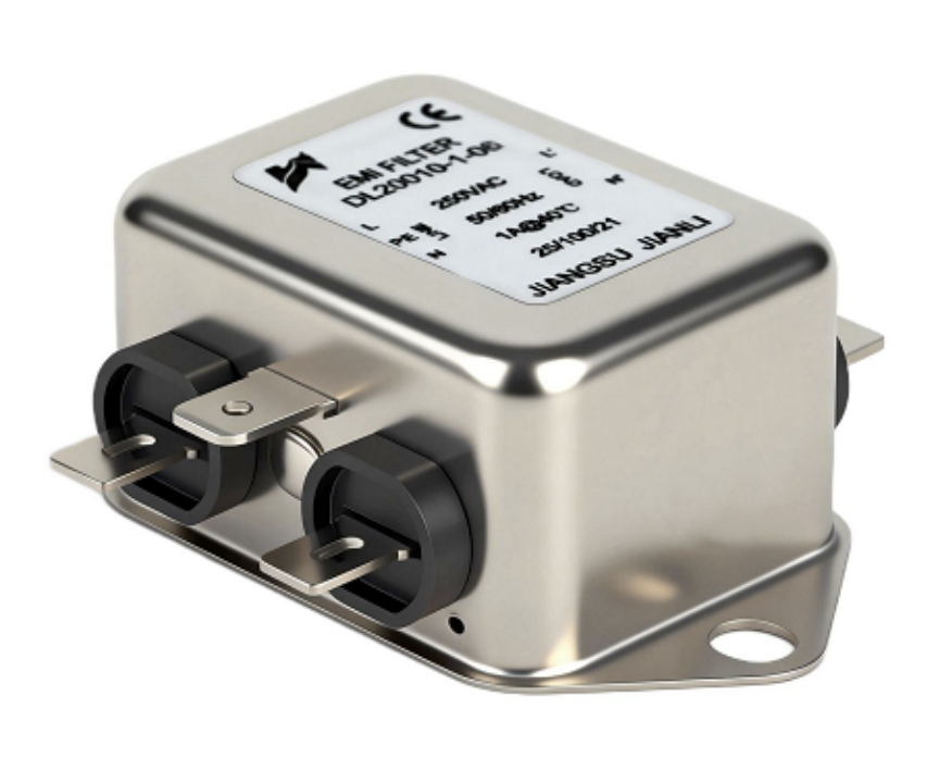
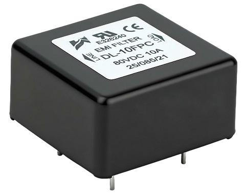
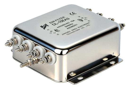
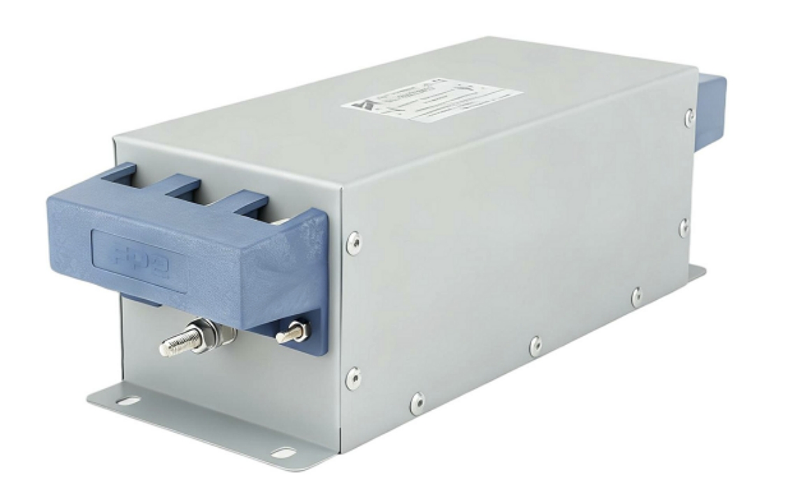
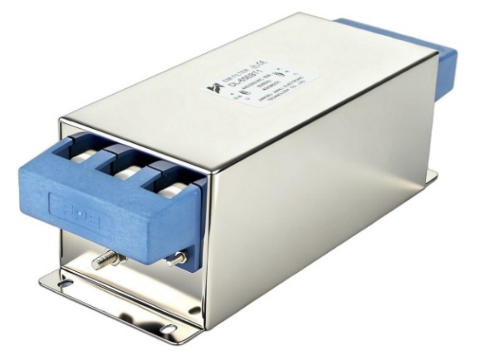
A dv/dt filter is a passive LC network installed between a variable frequency drive (VFD) and a motor to limit the rate of voltage rise (dv/dt) generated by IGBT switching. It protects motor winding insulation, reduces bearing currents, and ensures EMC compliance in industrial drive systems.
1. What Is a Dv/dt Filter?
A dv/dt filter is an inductor-capacitor (LC) passive filter designed to attenuate steep voltage transients produced by pulse-width modulated (PWM) inverters. Modern IGBTs switch at rates exceeding 10,000 V/µs, generating reflected wave voltages that can reach 2× DC bus voltage at the motor terminals.
Core function:
- Limits voltage rise rate to ≤500 V/µs (IEC 60034-17 recommended threshold)
- Reduces peak terminal voltage overshoot
- Suppresses high-frequency common-mode and differential-mode noise
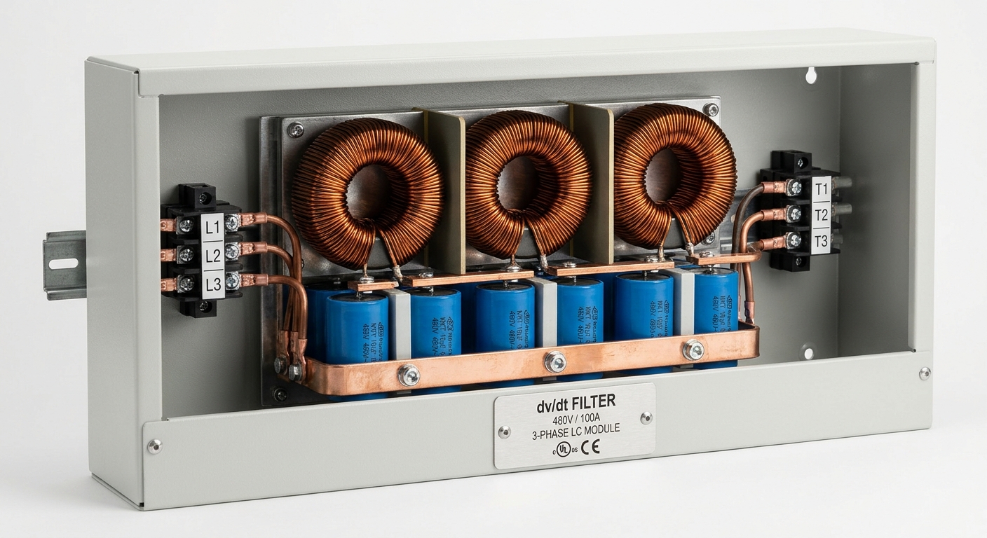
Key components:
- Series inductors (per phase): typically 0.5–5 mH
- Shunt capacitors: typically 0.1–2 µF, rated for continuous AC duty
- Optional damping resistors for resonance control
Operating principle: The LC network forms a low-pass filter. Rise time is extended from nanoseconds to microseconds, reducing dv/dt from >5,000 V/µs to <500 V/µs. Cutoff frequency is typically set at 2–5× the carrier frequency but well below the PWM switching frequency.
| Parameter | Without dv/dt Filter | With dv/dt Filter |
|---|---|---|
| Peak dv/dt | 5,000–15,000 V/µs | 200–500 V/µs |
| Terminal voltage overshoot | Up to 2× DC bus | <1.1× DC bus |
| Rise time | 50–200 ns | 1–10 µs |
| Common-mode noise attenuation | Baseline | 20–40 dB reduction |
2. How IGBT Switching Speed Degrades Motor Winding Insulation
2.1 The Reflected Wave Phenomenon
When a VFD output voltage pulse travels along a motor cable, impedance mismatch between the cable (typically 50–150 Ω) and motor windings (typically 1,000–5,000 Ω) causes voltage reflection. The reflected wave adds to the incident wave, producing overvoltage at motor terminals.
Critical relationship:
- Cable length >30 m: full voltage doubling risk
- Cable length 10–30 m: partial reflection, 1.3–1.8× overshoot
- Cable length <10 m: minimal reflection effect
2.2 Insulation Degradation Mechanism
IGBT switching speed directly determines partial discharge (PD) inception voltage stress on winding insulation.
Degradation pathway:
- High dv/dt → elevated electric field stress across turn-to-turn insulation
- Partial discharge initiates at voids in enamel coating
- Each PD event erodes insulation by 0.01–0.1 µm per pulse
- At 10 kHz carrier frequency: >600 million stress cycles per day
IEC 60034-18-41 classifies motor insulation into:
- Type I: Standard insulation, rated for ≤500 V/µs, suitable with dv/dt filter
- Type II: Inverter-duty insulation, rated for ≤1,500 V/µs without filter
Without a dv/dt filter on a 480 V drive with 50 m cable, insulation life can reduce from 20 years to under 3 years based on Arrhenius degradation modeling.
3. Bearing Current Damage and dv/dt Threshold Values
3.1 Bearing Current Generation Mechanisms
PWM switching creates high-frequency common-mode voltage (CMV) on the motor shaft. Three distinct bearing current types result:
| Bearing Current Type | Trigger Condition | Damage Threshold |
|---|---|---|
| Capacitive discharge (EDM) | CMV >10 V peak, dv/dt >1,000 V/µs | Frosting/fluting after 10⁸ pulses |
| Circulating bearing current | Motor frame >100 kW, cable >10 m | Shaft voltage >500 mV (peak) |
| Rotor ground current | Long cables, unshielded | >100 mA high-frequency ground current |
3.2 Threshold Values for Bearing Damage
- EDM current threshold: >200 mA peak discharge triggers pitting within 500 operating hours
- Shaft voltage threshold: >10 V peak-to-peak (NEMA MG1 Part 31 guideline)
- Critical dv/dt level: >2,000 V/µs significantly elevates bearing current amplitude
- Bearing current density: >0.5 A/mm² causes lubricant carbonization within 1,000 hours
A dv/dt filter reducing switching transients from 8,000 V/µs to 400 V/µs decreases capacitive bearing current by a factor of 15–20×, measured per IEEE 1100 methodology.
4. How dv/dt Filters Attenuate Voltage Transients in Long Cable Runs
4.1 Cable Length vs. Filter Selection
The motor dv/dt filter must be sized based on cable impedance, length, and VFD carrier frequency. Industrial dv/dt filter manufacturers specify cable length ratings in product datasheets.
Selection criteria by cable length:
- 0–30 m: Basic RC snubber or output reactor may suffice
- 30–100 m: Standard dv/dt filter required; target <500 V/µs
- >100 m: High-attenuation dv/dt filter or sine wave filter required; target <200 V/µs
4.2 Attenuation Performance Data
An inverter dv/dt filter with the following specifications provides measurable protection:
- Inductance per phase: 2 mH
- Capacitance: 0.47 µF (Y-connected)
- Cutoff frequency: ~5.2 kHz
- Insertion loss at 10 kHz: 28 dB
- Voltage drop at rated current: <2% (full load)
For a 100 m shielded cable run at 480 V, 10 kHz carrier frequency, a properly sized industrial dv/dt filter reduces terminal overvoltage from 960 V peak to under 520 V peak, keeping stress within IEC 60034-17 limits.
5. EMC Compliance: Comparing dv/dt Filter Topologies
5.1 Topology Comparison
| Filter Topology | dv/dt Attenuation | Common-Mode Suppression | Output Waveform | Relative Cost |
|---|---|---|---|---|
| RC Snubber | Low (<30%) | None | PWM | Low |
| Output Reactor (inductor only) | Moderate (40–60%) | Minimal | PWM | Low–Medium |
| dv/dt Filter (LC) | High (70–90%) | 20–35 dB | Modified PWM | Medium |
| Sine Wave Filter | Very High (>95%) | 35–55 dB | Near-sinusoidal | High |
5.2 EMC Standards Applicability
- IEC 61800-3: Governs conducted and radiated emissions from VFD systems; dv/dt filters reduce conducted emissions by 15–25 dB in the 150 kHz–30 MHz range
- CISPR 11: Industrial equipment emission limits; an EMI EMC power filter combined with a dv/dt filter achieves Class A compliance in most configurations
- EN 55011: Equivalent European standard; dv/dt filter topology selection directly impacts compliance margin
Key differentiator: A sine wave filter achieves superior EMC performance but introduces 3–5% efficiency loss and requires motor derating. An industrial dv/dt filter offers the optimal balance for most VFD applications without motor derating.
6. Carrier Frequency Impact on dv/dt Filter Sizing
Carrier frequency is the primary variable governing dv/dt filter thermal rating and cutoff frequency selection.
Engineering relationships:
- Higher carrier frequency → higher switching losses in filter inductors → increased thermal derating required
- Typical carrier frequency range: 2–16 kHz for industrial VFDs
- Filter cutoff frequency must satisfy: f_cutoff < f_carrier / 3 to prevent filter resonance amplification
Sizing table by carrier frequency:
| Carrier Frequency | Recommended Cutoff Frequency | Inductor Core Material | Thermal Derating Factor |
|---|---|---|---|
| 2–4 kHz | 0.8–1.5 kHz | Silicon steel | 1.0× |
| 4–8 kHz | 1.5–3.0 kHz | Amorphous/nanocrystalline | 0.85× |
| 8–16 kHz | 3.0–5.5 kHz | Ferrite/nanocrystalline | 0.70× |
A dv/dt filter for VFD operating at 8 kHz carrier requires nanocrystalline core inductors to limit core losses below 1.5 W/kg. Silicon steel cores at this frequency exhibit losses exceeding 8 W/kg, causing premature thermal failure.
7. Real-World Application Scenarios
Scenario 1 — Pump Station with 75 m Cable Run:
A water utility deployed 132 kW VFDs driving submersible pumps via 75 m armored cables. Without filtering, motor insulation failures occurred within 18 months. After installing motor dv/dt filters (2 mH/0.47 µF, 160 A rated), terminal dv/dt dropped from 7,200 V/µs to 380 V/µs. No insulation failures recorded over 4 subsequent years.
Scenario 2 — CNC Machine Tool Spindle Drive:
A precision machining facility experienced bearing fluting on 15 kW spindle motors within 6 months. Shaft voltage measurements showed 18 V peak-to-peak. After installing an inverter dv/dt filter combined with insulated bearings, shaft voltage dropped to 2.1 V peak-to-peak. Bearing replacement interval extended from 6 months to >36 months.
Scenario 3 — HVAC Chiller Plant EMC Compliance:
A commercial building’s chiller VFDs failed CISPR 11 Class A conducted emission tests at 3 MHz by 12 dB. Retrofitting EMI EMC power filters with integrated dv/dt filtering achieved 18 dB margin below Class A limits, enabling building management system certification.
FAQ: dv/dt Filter — Common Technical Questions
Q1: What is the standard dv/dt limit for motor protection?
IEC 60034-17 recommends ≤500 V/µs for standard motors.
Q2: Can a dv/dt filter replace a sine wave filter?
No; sine wave filters achieve near-sinusoidal output; dv/dt filters only limit rise rate.
Q3: Where is a dv/dt filter installed?
At the VFD output terminals, before the motor cable.
Q4: Does a dv/dt filter affect motor efficiency?
Voltage drop is typically <2%; efficiency impact is negligible at full load.
Q5: What certifications should a dv/dt filter carry?
UL 508C, CE marking, and IEC 61800-3 compliance are standard requirements.
Q6: How is dv/dt filter sizing determined?
By motor kW rating, VFD carrier frequency, cable length, and supply voltage.
Q7: Can one dv/dt filter serve multiple motors?
No; each motor-VFD pair requires an individually sized filter.
Q8: What distinguishes a quality dv/dt filter manufacturer?
Verified insertion loss data, thermal ratings per carrier frequency, and UL/CE certification.
Conclusion
A dv/dt filter is a precision-engineered passive LC network that directly addresses the three primary failure mechanisms in VFD-motor systems: winding insulation degradation, bearing current damage, and EMC non-compliance. Engineering data consistently shows that limiting dv/dt to ≤500 V/µs extends motor insulation life by 5–7× and reduces bearing current by up to 20×.
Selection checklist for engineers and procurement managers:
- Confirm cable length and determine required attenuation level
- Match filter cutoff frequency to VFD carrier frequency (f_cutoff < f_carrier/3)
- Verify continuous current rating at operating temperature
- Require UL 508C and IEC 61800-3 certification from any dv/dt filter supplier or dv/dt filter factory
- Evaluate dv/dt filter manufacturer’s published insertion loss curves at your specific carrier frequency
For systems exceeding 100 m cable runs or requiring sinusoidal motor voltage, evaluate sine wave filter alternatives. For the majority of industrial VFD applications between 30–100 m cable runs, a properly selected industrial dv/dt filter delivers optimal protection at the lowest total cost of ownership.
References & Standards:
- IEC 60034-17: Rotating Electrical Machines — Cage Induction Motors When Fed from Converters
- IEC 60034-18-41: Qualification and Acceptance Tests for Partial Discharge Resistant Electrical Insulation Systems
- IEC 61800-3: Adjustable Speed Electrical Power Drive Systems — EMC Requirements
- NEMA MG1 Part 31: Definite-Purpose Inverter-Fed Polyphase Motors
- IEEE Std 1100: Powering and Grounding Electronic Equipment
- CISPR 11 / EN 55011: Industrial, Scientific and Medical Equipment — Radio-Frequency Disturbance Characteristics
- Mohan, N., Undeland, T.M., Robbins, W.P. (2003). Power Electronics: Converters, Applications, and Design. Wiley.