
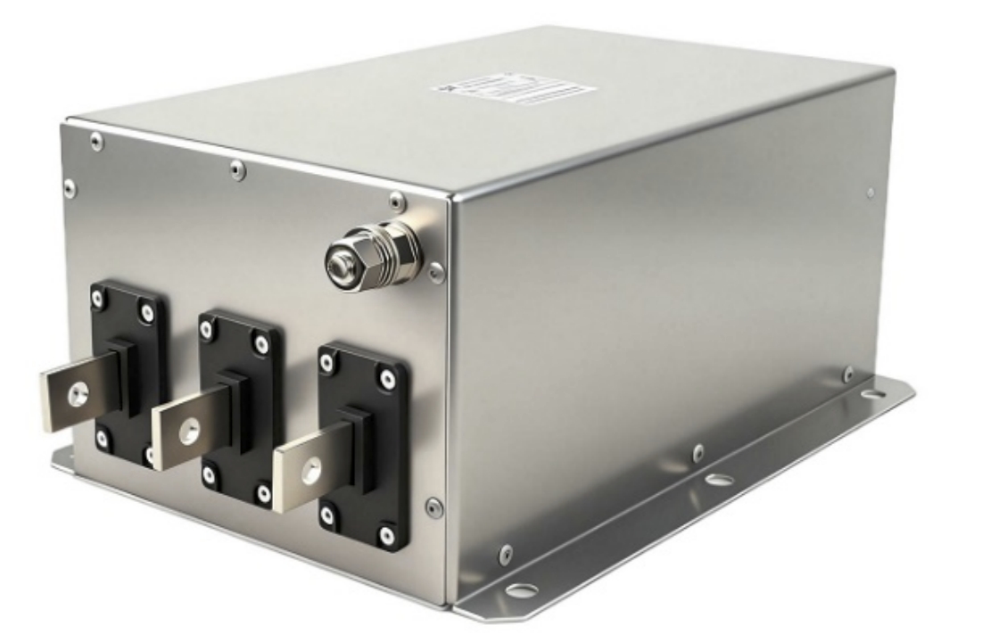
Abstract
Variable frequency drives (VFDs) are indispensable in modern industrial operations, delivering precise motor speed control and significant energy savings. However, they introduce a critical power quality challenge: harmonic distortion. As nonlinear loads, VFDs draw pulsed, non-sinusoidal currents from the supply network, injecting harmonic frequencies that propagate throughout the electrical system.
Left unmitigated, this harmonic noise causes transformer overheating, premature capacitor failure, nuisance tripping of sensitive equipment, and measurable reductions in overall system efficiency. For facilities operating multiple VFDs—common in HVAC, pumping, and oil and gas sectors—the cumulative harmonic burden can push Total Harmonic Distortion (THD) far beyond acceptable thresholds.
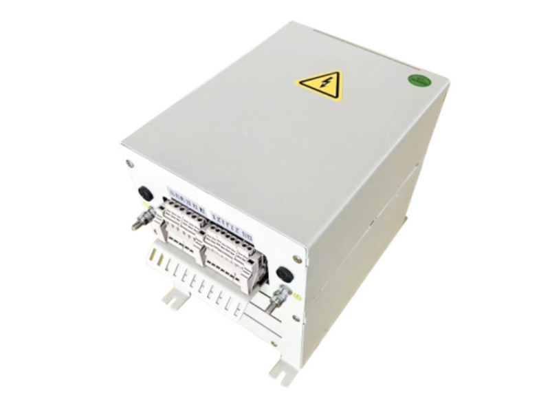
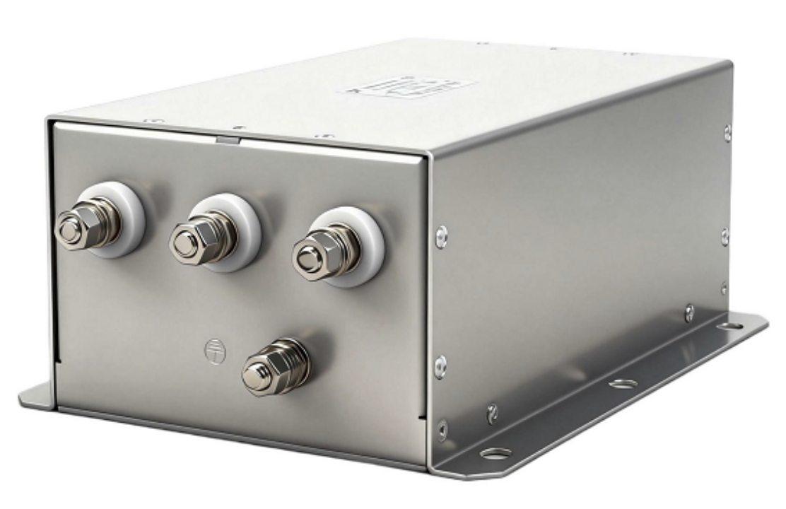
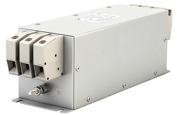
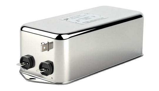
This article examines how passive harmonic filters, built around precision-tuned LC circuits, provide a robust, cost-effective solution to VFD-generated harmonic noise. We cover the physics of harmonic generation, filter topology selection, IEEE 519 compliance requirements, and the commercial case for passive filtration in B2B industrial environments.
1: Understanding VFD Harmonic Noise and Its Industrial Impact
1.1: How VFDs Generate Harmonic Distortion
VFDs operate through a three-stage power conversion process: an input rectifier converts AC to DC, a DC bus stores energy, and an inverter reconstructs variable-frequency AC for the motor. The front-end rectifier—typically a six-pulse diode bridge—is the primary harmonic source. Unlike linear loads that draw sinusoidal current, this rectifier draws current in discrete pulses synchronized with the AC voltage peaks.
This pulsed current waveform, when decomposed via Fourier analysis, contains the fundamental frequency (50 or 60 Hz) plus a series of harmonic components. For a standard six-pulse VFD, the dominant harmonics follow the formula h = (n × p) ± 1, where p is the pulse number and n is any positive integer. This yields characteristic harmonic orders of 5th, 7th, 11th, and 13th—the 5th and 7th being the most energetically significant, typically carrying 20–25% and 10–14% of fundamental current magnitude respectively.
Twelve-pulse and eighteen-pulse VFD configurations cancel lower-order harmonics through phase-shifting transformers, but they add capital cost and are impractical for retrofit applications. This is precisely where passive harmonic filters deliver their greatest value.
1.2: Consequences for Equipment and Power Quality
Harmonic currents flowing through system impedances create harmonic voltages that distort the supply waveform for every connected load. The consequences are both immediate and cumulative:
- Transformer overheating: Harmonic currents increase eddy current and stray losses. A transformer operating with 15% THD-I may experience a 10–15% reduction in rated capacity.
- Capacitor bank failure: Power factor correction capacitors present low impedance at harmonic frequencies, attracting disproportionate harmonic current and accelerating dielectric breakdown.
- Sensitive equipment malfunction: PLCs, metering systems, and UPS units are vulnerable to voltage distortion, causing erratic operation, data errors, and false protective relay trips.
- Motor heating and derating: Harmonic voltages in motor windings generate parasitic torques and additional I²R losses, shortening insulation life.
- Utility penalty exposure: Many grid operators enforce harmonic limits at the Point of Common Coupling (PCC), with non-compliance resulting in financial penalties or forced power factor corrections.
2: How a Passive Harmonic Filter Works — Tuned LC Circuit Principles
2.1: Core Architecture of a Tuned LC Filter
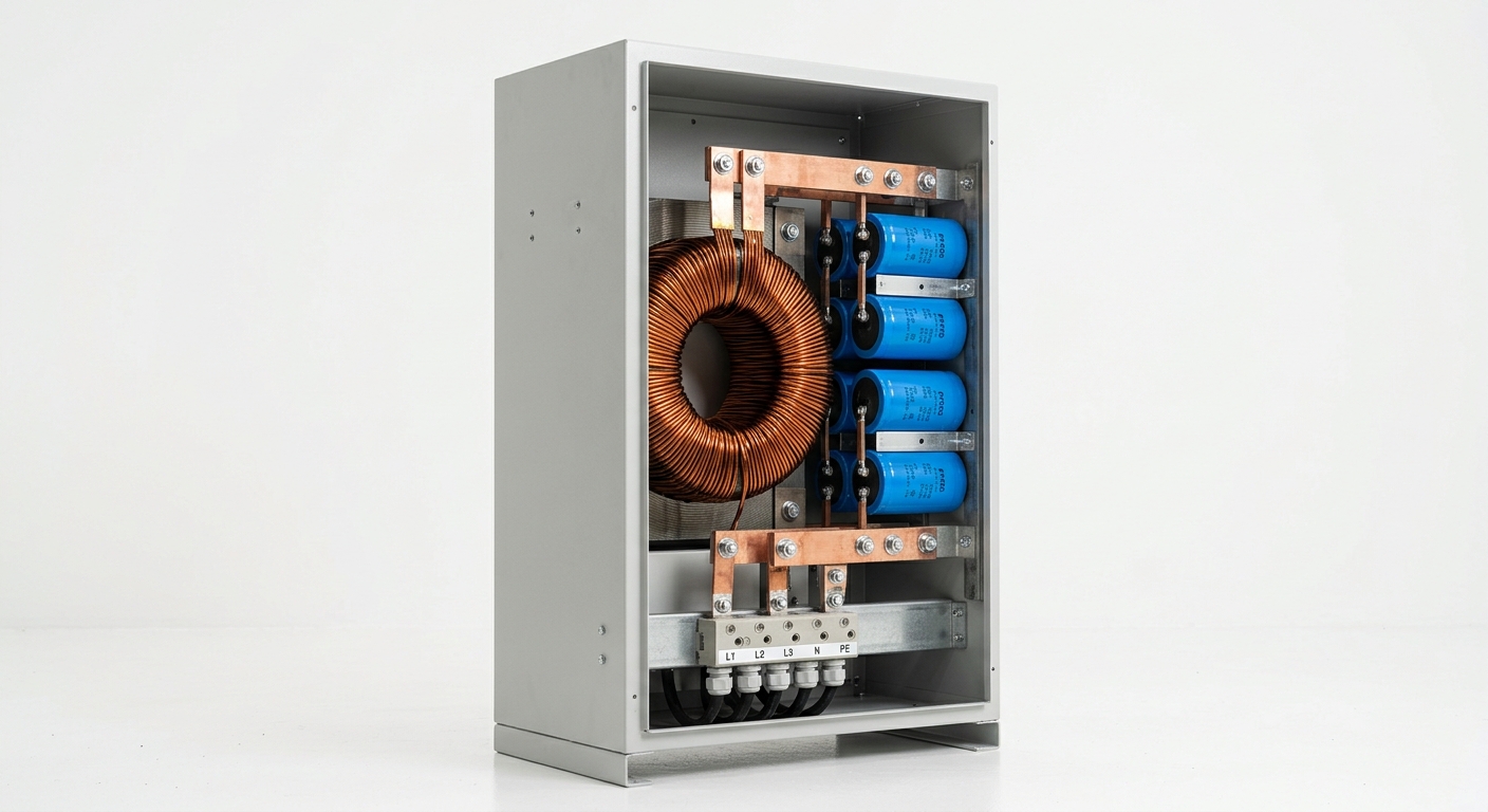
A passive harmonic filter is fundamentally a frequency-selective impedance network. Its core element is a series LC resonant circuit connected in shunt (parallel) with the load. The inductor (L) and capacitor (C) are sized so that their series resonant frequency matches the target harmonic:
f_r = 1 / (2π√LC)
At resonance, the series LC circuit presents near-zero impedance to the target harmonic frequency. This creates a low-resistance path that diverts harmonic current away from the supply network and into the filter branch, preventing it from propagating upstream. The filter is typically tuned slightly below the target harmonic order (e.g., tuned to 4.7th order to suppress the 5th harmonic) to avoid resonance amplification caused by system impedance variations.
The shunt connection is critical: it does not interrupt the load’s fundamental current path, ensuring no impact on drive operation. The capacitor bank simultaneously provides reactive power compensation, improving displacement power factor—a dual benefit that enhances the commercial proposition.
2.2: Single-Tuned vs. Double-Tuned Filter Topologies
Single-tuned filters target one harmonic order per filter branch. For a six-pulse VFD, a typical installation deploys two branches: one tuned to the 5th harmonic and one to the 7th. This approach offers precise attenuation at specific frequencies with straightforward commissioning, making it the preferred choice for applications where the harmonic spectrum is well-defined and stable.
Double-tuned filters combine two resonant frequencies within a single filter structure, reducing component count and footprint. They are preferred in space-constrained installations or when addressing both 5th and 7th harmonics simultaneously with a single unit. However, their design is more complex, and detuning due to component aging can simultaneously affect both target frequencies.
High-pass filters offer broadband attenuation above a cutoff frequency and are used to suppress higher-order harmonics (11th, 13th, and above) in large industrial installations.
📊 Passive Harmonic Filter Topology Comparison
| Parameter | Single-Tuned | Double-Tuned | High-Pass |
|---|---|---|---|
| Filter Type | Single-Tuned | Double-Tuned | High-Pass |
| Target Harmonic Orders | 5th or 7th (per branch) | 5th & 7th (combined) | 11th, 13th, and above |
| Typical THD Suppression | 70–85% per branch | 75–88% combined | 50–70% broadband |
| Applicable VFD Power Range | 7.5–2000 kW | 30–2000 kW | 100 kW+ |
| IEEE 519 Compliance | Yes (with proper sizing) | Yes | Supplementary |
| Installation Method | Shunt (parallel) | Shunt (parallel) | Shunt (parallel) |
3: IEEE 519 Compliance — Standards, Limits, and Selection Criteria
3.1: Key IEEE 519 Requirements for VFD Applications
IEEE 519-2022 establishes harmonic limits at the Point of Common Coupling (PCC)—the interface between the utility and the customer’s facility. The standard defines two primary metrics:
- Total Demand Distortion (TDD): Current harmonic distortion expressed as a percentage of maximum demand load current (I_L). Limits range from 5% TDD (for systems with short-circuit ratio ISC/IL < 20) up to 20% TDD (for ISC/IL > 1000).
- Total Harmonic Distortion (THD-V): Voltage distortion limits at the PCC, typically 5% for systems below 69 kV in general industrial applications.
For most industrial facilities with multiple VFDs, achieving TDD below 8% at the PCC requires active harmonic mitigation. A properly designed passive harmonic filter system can reduce current THD at the drive terminals from a typical 30–40% down to 8–12%, bringing the aggregate PCC measurement within IEEE 519 limits.
3.2: Selecting the Right Passive Harmonic Filter for Compliance
Correct filter selection requires a systematic engineering assessment:
- Short-Circuit Ratio (SCR) evaluation: The ratio of available fault current to load current determines the system’s “stiffness.” Low SCR systems (weak grids) are more susceptible to harmonic voltage distortion and require higher-performance filters.
- Harmonic load flow analysis: A site power quality survey identifies the actual harmonic spectrum, load variability, and existing background distortion before filter sizing.
- Detuning risk management: If the utility adds capacitor banks or system impedance changes, filter resonant frequency may shift. Detuning protection—typically a reactor with ±5% inductance tolerance—must be specified.
- Capacity matching: The filter’s reactive power output must be matched to the VFD’s reactive demand to avoid leading power factor at light loads, which can cause overvoltage conditions.
4: Application Scenarios and Commercial Value
4.1: Typical Industrial Use Cases
Passive harmonic filters deliver measurable value across a broad range of VFD-intensive applications:
- HVAC systems: Large chiller plants and AHU fan arrays with multiple VFDs create significant harmonic loading on building distribution systems. Passive filters protect BMS controllers and metering infrastructure.
- Water and wastewater pumping stations: Pump VFD groups operating continuously represent ideal passive filter candidates due to stable, predictable harmonic profiles.
- Compressor drives: Oil and gas upstream and midstream facilities running high-power compressor VFDs (500 kW–5 MW) face strict utility harmonic requirements and benefit from robust passive filter installations.
- Data center UPS front-ends: Passive filters upstream of UPS systems reduce harmonic injection onto the facility bus, protecting critical IT infrastructure.
- Industrial manufacturing: CNC machining centers, press drives, and conveyor systems with variable-speed motors generate 5th and 7th harmonic currents that passive filters efficiently suppress.
4.2: ROI and Total Cost of Ownership for B2B Buyers
The financial case for passive harmonic filters is compelling when evaluated against the full cost of harmonic-related losses:
- Reduced equipment downtime: Eliminating harmonic-induced failures in transformers, capacitor banks, and sensitive electronics directly reduces unplanned maintenance costs.
- Extended asset life: Reducing transformer harmonic losses by 80% can extend transformer service life by 5–10 years, deferring capital replacement expenditure.
- Utility compliance: Avoiding harmonic penalty clauses and power factor surcharges delivers immediate, recurring savings.
- Passive vs. Active Filter (APF) cost comparison: Active harmonic filters offer superior dynamic performance and load adaptability, but carry 3–5× higher capital cost and require ongoing maintenance of power electronics. For applications with stable, predictable harmonic loads—the majority of VFD installations—passive filters deliver equivalent IEEE 519 compliance at significantly lower total cost of ownership.
Typical payback periods for passive harmonic filter installations range from 12 to 30 months, depending on facility size, utility tariff structure, and baseline harmonic severity.
FAQ
Q1: What is the difference between a passive harmonic filter and an active harmonic filter for VFD applications?
Passive harmonic filters use fixed LC resonant circuits to divert specific harmonic frequencies; they are robust, maintenance-free, and cost-effective for stable harmonic loads. Active harmonic filters (APF) use power electronics to inject compensating currents in real time, adapting to variable loads. APFs are superior for dynamic or unpredictable harmonic profiles but cost significantly more and require periodic maintenance of their inverter components.
Q2: How do I determine if my facility requires a passive harmonic filter to meet IEEE 519 standards?
Conduct a power quality audit using a power analyzer at the PCC and at individual VFD input terminals. If measured TDD exceeds the IEEE 519 limit applicable to your facility’s ISC/IL ratio, or if THD-V at the PCC exceeds 5%, harmonic mitigation is required. A harmonic load flow study will confirm whether passive filtering at the drive level is sufficient or whether a centralized filter bank is needed.
Q3: Can a passive harmonic filter cause resonance issues in my existing power system?
Yes, if improperly designed. A shunt passive filter can form a parallel resonant circuit with existing power factor correction capacitors or transformer leakage reactance, potentially amplifying certain harmonic orders rather than suppressing them. This risk is mitigated through thorough system impedance analysis prior to filter specification, correct detuning of the filter resonant frequency, and coordination with any existing reactive compensation equipment.
Conclusion
Passive harmonic filters represent the most technically mature and commercially viable solution for eliminating VFD-generated harmonic noise in industrial power systems. By leveraging precision-tuned LC circuits to create low-impedance shunt paths for dominant harmonic orders—particularly the 5th and 7th—these filters reduce current THD from 30–40% at the drive terminals to levels fully compliant with IEEE 519 TDD requirements.
Beyond compliance, the commercial value is substantial: reduced transformer and capacitor losses, elimination of sensitive equipment malfunctions, extended asset service life, and avoidance of utility harmonic penalties combine to deliver ROI within 12–30 months in most industrial deployments.
For procurement engineers and facility managers evaluating harmonic mitigation strategies, the selection process should begin with a site power quality assessment to characterize the harmonic spectrum, followed by a system impedance analysis to ensure resonance-free filter integration. Our engineering team provides application-specific passive harmonic filter sizing, IEEE 519 compliance verification, and full technical documentation to support your procurement and installation process. Contact us today to initiate a harmonic assessment for your facility.