
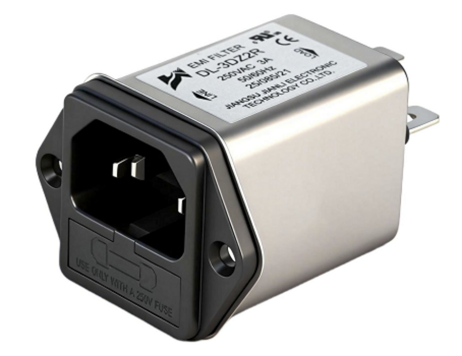
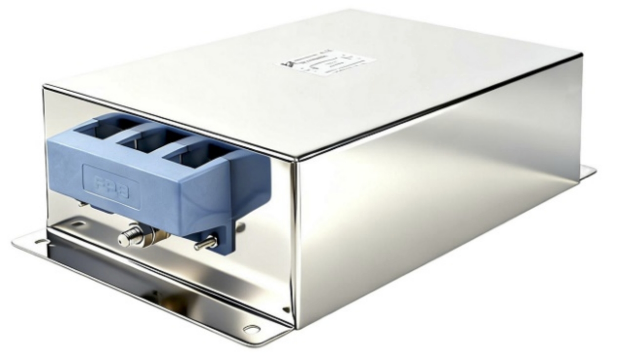
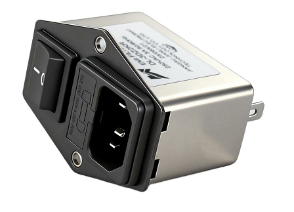
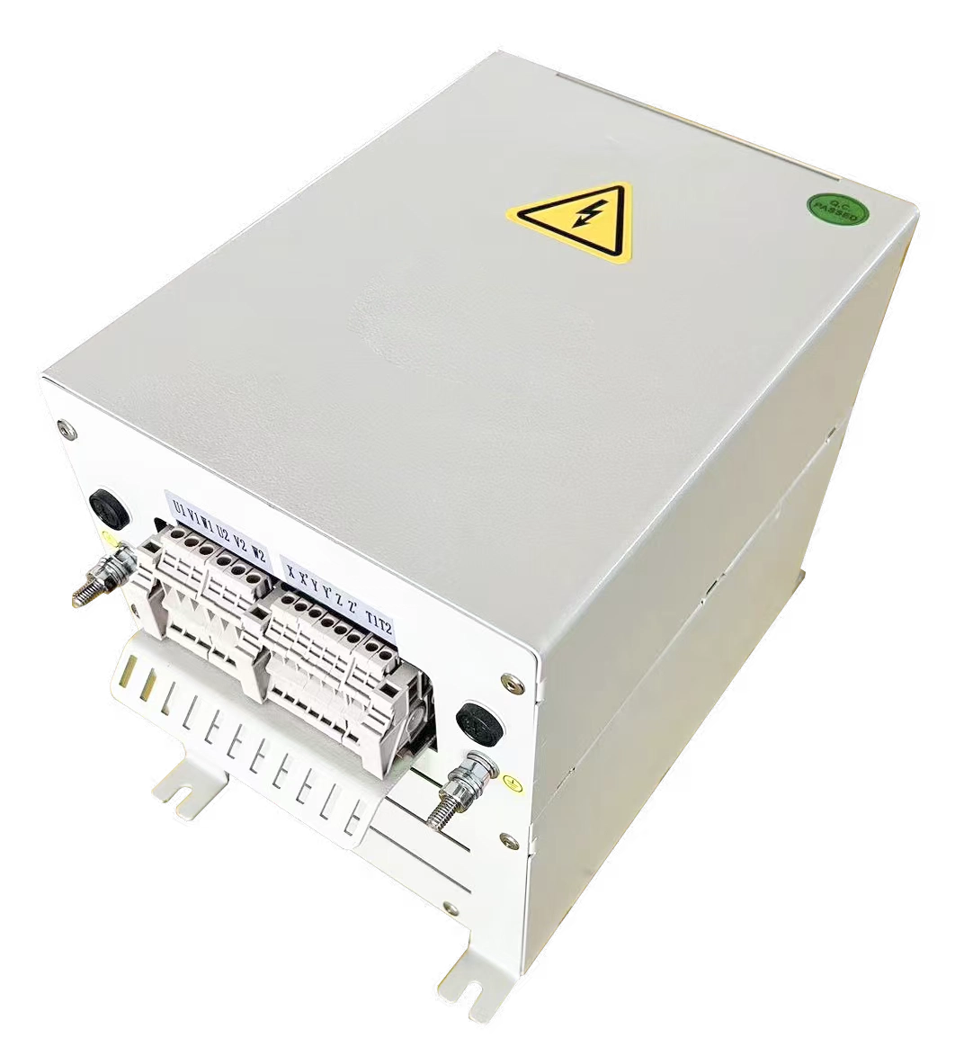
A passive harmonic filter uses tuned LC circuits to suppress specific harmonic frequencies generated by nonlinear loads. It reduces total harmonic distortion (THD-I) to below 8%, improves power factor, and protects equipment without requiring external power.
What Is a Passive Harmonic Filter and How Does It Work?
A passive harmonic filter is a fixed-tuned electrical network composed of inductors (L) and capacitors (C) arranged in series-resonant branches. Each branch is tuned to a target harmonic order—typically the 5th (300 Hz), 7th (420 Hz), 11th (660 Hz), or 13th (780 Hz) in 50 Hz systems.
Operating Principle
- Series resonance creates a low-impedance path at the tuned frequency, diverting harmonic current away from the supply network.
- Detuning factor (p-factor) is typically set at 0.94–0.97 to avoid resonance with the fundamental frequency.
- Filters are connected in shunt (parallel) with the nonlinear load at the point of common coupling (PCC).
- No external power supply is required; the filter is entirely passive.
Key Electrical Parameters
| Parameter | Typical Specification |
|---|---|
| Harmonic Attenuation (5th) | ≥ 85% reduction |
| THD-I at Full Load | < 8% (IEEE 519-2022) |
| Power Factor Correction | 0.85 → 0.95+ |
| Operating Voltage | 380 V – 690 V (LV) |
| Frequency Range | 50 Hz / 60 Hz |
| Detuning Factor (p) | 0.94 – 0.97 |
The filter’s resonant frequency is calculated as: f_r = f₁ / √p, where f₁ is the fundamental frequency and p is the detuning factor.
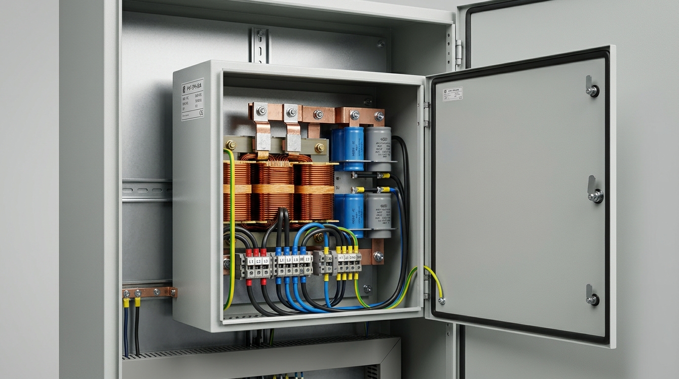
Where Are Passive Harmonic Filters Commonly Used?
Passive harmonic filters are deployed wherever nonlinear loads—particularly variable frequency drives (VFDs)—generate significant harmonic distortion. Their cost-effectiveness and reliability make them the preferred solution across multiple sectors.
Industrial Applications by Sector
| Industry | Typical Load | Primary Harmonic Orders |
|---|---|---|
| Industrial Manufacturing | CNC machines, VFDs, rectifiers | 5th, 7th |
| HVAC & Building Systems | Chiller drives, AHU fans | 5th, 7th, 11th |
| Water & Wastewater Treatment | Pump drives, blowers | 5th, 7th |
| Data Centers | UPS systems, server PSUs | 3rd, 5th |
| Mining & Heavy Industry | Conveyor drives, crushers | 5th, 7th, 11th, 13th |
| Oil & Gas | Compressor drives, ESP pumps | 5th, 7th |
| Renewable Energy | Solar inverters, wind converters | 5th, 7th, 11th |
Real-World Use Cases
Case 1 — Automotive Manufacturing Plant:
A 2.4 MW stamping facility with 18 VFDs recorded THD-I of 42%. After installing a 5th/7th tuned passive harmonic filter bank at the MCC bus, THD-I dropped to 6.3%, eliminating transformer overheating and reducing monthly energy losses by approximately 3.2%.
Case 2 — Municipal Water Treatment Station:
A pumping station operating twelve 75 kW drives experienced nuisance tripping of protective relays. Shunt passive filters tuned to the 5th harmonic reduced THD-I from 38% to 7.1%, restoring relay stability and extending motor insulation life.
Case 3 — Commercial Data Center:
A 1.5 MW facility with high 3rd-harmonic content from IT loads installed a 3rd/5th passive filter combination, reducing neutral conductor overloading by 61% and improving PF from 0.78 to 0.93.
What Is the Difference Between Passive and Active Harmonic Filters?
Choosing between a passive harmonic filter and an active harmonic filter (AHF) is a critical decision in any power quality improvement project. Both technologies address harmonic distortion but differ fundamentally in architecture, cost, and performance range.
Passive vs. Active Harmonic Filter: Technical Comparison
| Criterion | Passive Harmonic Filter | Active Harmonic Filter |
|---|---|---|
| Operating Principle | Fixed LC resonant circuit | Real-time current injection (DSP-controlled) |
| Harmonic Orders Addressed | Fixed (e.g., 5th, 7th) | Dynamic (2nd–50th) |
| THD-I Performance | < 8% (at rated load) | < 5% (across load range) |
| Load Sensitivity | Degrades at partial load | Consistent at 20%–100% load |
| Power Consumption | Zero (passive) | 1%–3% of rated kVA |
| Initial Cost (per kVA) | Low ($15–$40/kVA) | High ($80–$200/kVA) |
| Maintenance | Minimal (capacitor inspection) | Moderate (IGBT, cooling system) |
| Power Factor Correction | Inherent (leading PF) | Adjustable |
| Best Application | Fixed, high-load VFD systems | Variable, multi-load environments |
Selection Guidance
- Choose passive when: load is stable (>70% rated), harmonic spectrum is predictable (6-pulse VFDs), and budget is constrained.
- Choose active when: load varies significantly, multiple harmonic orders are present, or space is limited.
- Hybrid approach: A passive filter handles dominant harmonics (5th, 7th); an active filter addresses residual and higher-order harmonics. This combination achieves THD-I < 3% at lower total cost.
How Do You Choose the Right Passive Harmonic Filter for an Industrial System?
Proper selection of a passive harmonic filter requires a structured engineering assessment. Incorrect sizing leads to resonance amplification, capacitor failure, or insufficient harmonic attenuation.
Step-by-Step Selection Process
Step 1 — Conduct a Power Quality Audit
- Measure baseline THD-I, THD-V, and harmonic spectrum using a Class A power quality analyzer (per IEC 61000-4-30).
- Identify dominant harmonic orders (typically 5th and 7th for 6-pulse VFDs).
Step 2 — Define the Target Standard
- IEEE 519-2022: THD-I ≤ 8% at PCC (for most industrial systems, ISC/IL > 20).
- IEC 61000-3-12: Applicable for equipment ≤ 75 A per phase at LV supply.
- EN 50160: Voltage harmonic limits for European utility connections.
Step 3 — Calculate Filter Rating
- Filter kVAR rating ≥ 30%–40% of VFD kVA for 5th-harmonic tuned filters.
- Account for load diversity factor when multiple VFDs share a bus.
Step 4 — Evaluate Key Specifications
| Specification | Engineering Requirement |
|---|---|
| Tuning Order | Match dominant harmonic (5th = 250 Hz at 50 Hz) |
| Detuning Factor | 0.94–0.97 (avoid fundamental resonance) |
| Reactor Quality Factor (Q) | ≥ 50 (minimizes insertion loss) |
| Capacitor Voltage Rating | ≥ 1.1× nominal voltage |
| Thermal Class | ≥ Class F (155°C) for industrial environments |
| IP Rating | IP20 (indoor) / IP54 (outdoor/harsh) |
Step 5 — Verify System Compatibility
- Perform harmonic load flow simulation (e.g., ETAP, SKM PowerTools) to confirm no parallel resonance with transformer impedance.
- Check utility short-circuit ratio (SCR) at PCC; low SCR (<20) increases resonance risk.
Can a Passive Harmonic Filter Improve Power Factor and Reduce Energy Losses?
Yes. A passive harmonic filter simultaneously performs harmonic suppression and reactive power compensation because its capacitive branches supply leading reactive power (kVAR) to the system.
Power Factor and Energy Impact
- A typical 5th/7th tuned passive filter improves displacement power factor from 0.75–0.85 to 0.92–0.97.
- Reduced harmonic current decreases I²R losses in cables, transformers, and motors.
- A 10% reduction in THD-I in a 1,000 kVA transformer system reduces copper losses by approximately 2–4 kW continuously.
- Improved PF reduces utility demand charges; facilities with 500 kVA loads typically save $8,000–$15,000/year in penalty avoidance.
Quantified Benefits Summary
- THD-I reduction: 35%–45% → below 8%
- Power factor improvement: +0.10 to +0.20 displacement PF
- Transformer derating recovery: Recovers 10%–15% of derated capacity
- Motor efficiency gain: 1%–3% improvement in motor operating efficiency
- Equipment lifespan extension: Reduces dielectric stress, extending capacitor and insulation life by 20%–30%
FAQ: Passive Harmonic Filter — Rapid Reference
Q1: What is a passive harmonic filter?
A tuned LC network that diverts harmonic currents from the power supply.
Q2: What THD level does a passive filter achieve?
Below 8% THD-I at full load per IEEE 519-2022.
Q3: Does a passive filter work with all VFD types?
Best suited for 6-pulse VFDs; less effective for 12-pulse or active front-end drives.
Q4: What is the typical lifespan of a passive harmonic filter?
15–20 years with annual capacitor inspection and replacement every 8–10 years.
Q5: Can one filter serve multiple VFDs?
Yes, when installed at the shared MCC bus; requires aggregate harmonic load calculation.
Q6: Does a passive filter cause leading power factor issues?
At light load (<30%), capacitive reactive power may cause leading PF; use a detuned reactor or automatic switching.
Q7: What standards govern passive harmonic filter performance?
IEEE 519-2022, IEC 61000-3-12, IEC 61000-4-7, and EN 50160.
Q8: What is the difference between a passive harmonic filter and a line reactor?
A line reactor reduces THD-I to ~30–35%; a passive filter achieves <8% THD-I.
Conclusion and Engineering Recommendations
A passive harmonic filter remains the most cost-effective solution for reducing harmonic distortion in industrial systems with stable, high-utilization nonlinear loads such as 6-pulse VFDs. It delivers THD-I below 8%, improves power factor by 0.10–0.20, and reduces energy losses without consuming power.
Key engineering recommendations:
- Always conduct a Class A power quality audit before filter selection.
- Size filter kVAR at 30–40% of VFD kVA for 5th-harmonic applications.
- Run a harmonic load flow simulation to verify no resonance risk.
- Apply IEEE 519-2022 as the primary compliance benchmark.
- For variable loads or multi-harmonic environments, evaluate a hybrid passive + active configuration.
- Specify IP54 enclosures and Class F thermal rating for harsh industrial environments.
For procurement teams and system integrators: evaluate suppliers against IEC 61000-4-7 test compliance, published insertion loss curves, and documented field THD measurement data.
References and Standards
- IEEE 519-2022: Recommended Practice and Requirements for Harmonic Control in Electric Power Systems
- IEC 61000-3-12: Limits for Harmonic Currents — Equipment with Input Current > 16 A
- IEC 61000-4-7: Testing and Measurement Techniques — General Guide on Harmonics
- IEC 61000-4-30: Power Quality Measurement Methods
- EN 50160: Voltage Characteristics of Electricity Supplied by Public Distribution Networks
- Dugan, R.C. et al. (2012). Electrical Power Systems Quality, 3rd ed. McGraw-Hill.
- Mohan, N., Undeland, T.M., & Robbins, W.P. (2003). Power Electronics, 3rd ed. Wiley.
- EPRI Report TR-1007423: Assessment of Harmonic Mitigation Options for Variable Speed Drives