
Abstract
In modern variable frequency drive (VFD) installations, the output reactor is one of the most consequential passive components between the inverter and the motor — yet it remains underspecified in many procurement cycles. Its primary role is to condition the inverter’s pulse-width modulated (PWM) output, attenuating the steep voltage rise rates (dV/dt) that switching transistors generate at microsecond intervals. Left unaddressed, these transients degrade motor winding insulation, induce bearing currents, and amplify electromagnetic interference across the system.
For OEM machine builders, plant engineers managing distributed motor loads, and procurement teams sourcing VFD accessories, understanding the output reactor’s function is not an academic exercise — it directly affects motor service life, unplanned downtime exposure, and total cost of ownership. This article provides a structured technical and commercial overview: how output reactors work, how to select and derate them correctly, which compliance standards apply, and where they deliver measurable ROI in real industrial environments.
1. The Core Function of an Output Reactor in a VFD System
1.1 How an Output Reactor Conditions Inverter Output
A VFD generates its variable-frequency, variable-voltage output through rapid IGBT switching — typically at carrier frequencies between 2 kHz and 16 kHz. Each switching event produces a PWM pulse with rise times as short as 50–200 nanoseconds. When these pulses travel through motor cables, the cable’s distributed capacitance and inductance create transmission-line effects: voltage reflections that can cause peak voltages at the motor terminals to reach 1.5–2× the DC bus voltage.
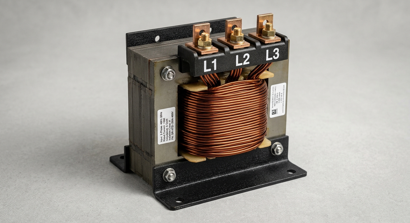
An output reactor — a three-phase series inductor installed between the VFD output terminals and the motor cable — directly opposes rapid changes in current (dI/dt), which in turn limits the rate of voltage rise (dV/dt). By inserting inductance values typically in the range of 1–5 mH, the reactor smooths the PWM waveform’s leading edges, reduces peak overvoltage at the motor terminals, and attenuates high-frequency switching noise that would otherwise propagate through the power circuit and radiate as EMI.
The practical result is a quasi-sinusoidal current waveform reaching the motor — significantly cleaner than the raw inverter output — which reduces thermal stress on motor windings and minimizes interference with adjacent sensitive equipment.
1.2 The Relationship Between Output Reactor and Motor Protection
The output reactor’s protective value extends beyond waveform shaping. Three specific failure mechanisms are mitigated:
- Insulation degradation: Repetitive high-dV/dt transients cause partial discharge within motor winding insulation, accelerating dielectric breakdown. An output reactor reduces this stress, extending insulation life — particularly important for standard (non-inverter-duty) motors.
- Bearing current damage: Common-mode currents induced by PWM switching can discharge through motor bearings, causing pitting and premature failure. The reactor’s impedance reduces the common-mode current path, lowering bearing current magnitude.
- Long-cable compatibility: Without an output reactor, cable runs beyond 20–30 meters significantly amplify reflection effects. With a properly rated reactor, motor cable lengths of 100 meters or more become manageable, giving system designers greater installation flexibility.
These protections are not redundant with other VFD accessories. A dV/dt filter provides more aggressive waveform conditioning but at higher cost and insertion loss; a sine-wave filter reconstructs a near-perfect sinusoid but introduces more impedance. The output reactor occupies an optimal middle ground for the majority of industrial motor applications.
2. Key Technical Parameters and Selection Criteria
2.1 Electrical Specifications That Define Performance
Selecting an output reactor requires matching several interdependent parameters to both the VFD and the motor load:
- Inductance (mH): Determines dV/dt suppression effectiveness. Higher inductance provides more attenuation but increases voltage drop. Typical values range from 0.5 mH (large drives, >200 A) to 5 mH (small drives, <10 A).
- Rated current (A): Must meet or exceed the VFD’s continuous output current rating. Undersizing causes saturation and thermal failure.
- Voltage rating: Must match the system voltage (e.g., 480 V, 600 V, or 690 V AC). Reactors are rated for the line voltage, not the PWM peak.
- Impedance percentage (%Z): Expressed as a percentage of the base impedance at rated current and frequency. A 3–5% impedance is the standard design target for output reactors, balancing protection against acceptable voltage drop.
- Frequency range: Most output reactors are designed for 50/60 Hz fundamental frequency. Variable-frequency operation (0–400 Hz for some servo applications) requires verification of core loss characteristics at elevated frequencies.
2.2 Derating Rules and Installation Constraints
Output reactors are rated at specific ambient temperatures (typically 40°C). Above this threshold, current capacity must be derated — commonly 1–2% per degree Celsius above the rated ambient. Enclosure mounting in warm control panels is a frequent source of field failures when derating is ignored.
Reference Selection Table:
| Power Range | Rated Current (A) | Inductance (mH) | Impedance (%Z) | Compatible VFD Examples | Max Cable Length (m) |
|---|---|---|---|---|---|
| 0.75–2.2 kW (1–3 HP) | 5–10 A | 3.5–5.0 | 3–5% | ABB ACS310, Siemens G120 | 100 |
| 3.7–7.5 kW (5–10 HP) | 16–25 A | 2.0–3.5 | 3–5% | Danfoss FC51, Yaskawa J1000 | 150 |
| 11–22 kW (15–30 HP) | 32–60 A | 1.0–2.0 | 3–5% | ABB ACS580, Allen-Bradley 525 | 200 |
| 30–75 kW (40–100 HP) | 75–150 A | 0.5–1.0 | 3–5% | Siemens S120, Danfoss FC302 | 250 |
| 90–160 kW (125–200 HP) | 180–310 A | 0.2–0.5 | 3–5% | ABB ACS880, Yaskawa A1000 | 300 |
Additional installation constraints include minimum clearance of 50 mm on all ventilated faces, vertical mounting orientation for natural convection cooling, and IP20 minimum enclosure rating for panel installation (IP54 or higher for exposed industrial environments).
3. Compliance Standards and Quality Benchmarks
3.1 Applicable International Standards
Output reactors used in VFD systems must conform to several overlapping regulatory frameworks:
- IEC 61800-3: The primary EMC standard for variable-speed drive systems. Output reactors contribute to conducted and radiated emission compliance, particularly relevant for installations in Category C2 and C3 environments.
- UL 508C: The North American standard for power conversion equipment. UL-listed output reactors are required for many industrial OEM applications sold into the U.S. and Canadian markets.
- CE Marking (Low Voltage Directive 2014/35/EU and EMC Directive 2014/30/EU): Mandatory for European market access. CE-marked reactors must demonstrate dielectric withstand, temperature rise, and short-circuit current ratings.
- RoHS Compliance: Increasingly required in procurement specifications, particularly for OEMs supplying into regulated end markets.
3.2 How Standards Influence Procurement Decisions
B2B buyers should structure vendor qualification around verifiable documentation, not self-declarations. A credible output reactor supplier should provide:
- Factory test reports per IEC 60076-6 (reactors and inductors) including inductance measurement, DC resistance, temperature rise, and insulation resistance data.
- Third-party certification certificates (UL file number, CE Declaration of Conformity) traceable to a named test laboratory.
- Material compliance declarations (RoHS, REACH) with substance verification.
- Derating curves for ambient temperature and altitude (above 1000 m, output current derating typically applies at 1% per 100 m).
Procurement teams that skip this documentation layer frequently encounter field failures traced back to non-compliant or counterfeit components — a risk that outweighs any unit cost savings.
4. Application Scenarios and Commercial Value
4.1 Where Output Reactors Deliver the Most Impact
Output reactors are not universally required, but they are strongly recommended — and in some cases essential — in the following scenarios:
- Long cable runs (>50 m): Reflection effects scale with cable length. Beyond 50 m, output reactors are considered best practice; beyond 100 m, they are near-mandatory without alternative filtering.
- High-cycle industrial environments: Applications with frequent start/stop cycles (conveyor systems, packaging machinery, press feeders) subject motor insulation to repetitive transient stress. Output reactors reduce per-cycle insulation degradation.
- Sensitive motor loads: Pumps, compressors, and HVAC fan motors — often standard-efficiency motors not rated for inverter duty — benefit most from output reactor protection. These motors lack the reinforced insulation of inverter-duty designs.
- Multi-motor configurations: When a single VFD drives multiple motors in parallel, an output reactor at the drive output prevents cross-coupling of switching transients between motor branches.
4.2 ROI Perspective — Protecting Assets and Reducing Downtime
The financial case for specifying an output reactor is straightforward when measured against motor replacement and downtime costs:
- A 30 kW industrial motor costs $1,500–$4,000 to replace, excluding labor, downtime, and process restart costs. A compatible output reactor typically represents 3–8% of that figure.
- Bearing failure caused by shaft currents — a direct consequence of unmitigated PWM switching — is one of the leading causes of unplanned motor downtime in VFD-driven systems. Output reactors reduce bearing current magnitude, directly extending bearing service intervals.
- For facilities operating continuous processes (water treatment, chemical processing, food and beverage), even a four-hour unplanned outage can generate costs that dwarf the capital cost of a complete reactor installation across an entire motor panel.
From a TCO perspective, output reactors belong in the baseline specification of any VFD system — not as an optional upgrade.
FAQ
1. What is the difference between an output reactor and a dV/dt filter in a VFD system?
An output reactor is a series inductor that limits dV/dt through its natural impedance to rapid current changes. A dV/dt filter combines inductors and capacitors to more aggressively clamp voltage rise rates to specific levels (e.g., <500 V/µs). dV/dt filters offer superior protection for very long cable runs or non-inverter-duty motors but introduce higher insertion loss and cost. Output reactors are the preferred solution for most standard applications.
2. How do I select the correct output reactor size for my variable frequency drive?
Match the reactor’s rated current to the VFD’s continuous output current (not the motor nameplate current). Select inductance and %Z within the 3–5% range for the drive’s power rating. Verify voltage rating matches system voltage and confirm derating requirements for your installation’s ambient temperature. Use the selection table in Section 2.2 as a starting reference.
3. Is an output reactor required by code, or is it optional for VFD installations?
Output reactors are not universally mandated by electrical codes, but they may be required by VFD manufacturer warranty conditions for cable runs exceeding specified lengths. They are also implicitly required for IEC 61800-3 EMC compliance in many installation categories. Regardless of code requirements, they represent engineering best practice for any installation where motor longevity and system reliability are priorities.
Conclusion
The output reactor performs a precise and non-redundant function in VFD systems: it conditions the inverter’s PWM output, suppresses dV/dt transients, protects motor insulation and bearings, and enables reliable operation across extended cable distances. Its selection requires attention to inductance, rated current, impedance percentage, and derating conditions — parameters that directly determine whether the reactor performs as specified under real operating conditions.
For procurement teams and system engineers, the compliance documentation framework outlined in Section 3 provides a practical qualification checklist. For facility managers evaluating capital expenditure, the TCO argument in Section 4 quantifies what is at stake when this component is omitted or undersized.
If you are specifying output reactors for a new VFD installation or upgrading an existing system, contact our engineering team for application-specific selection support and certified product documentation.