
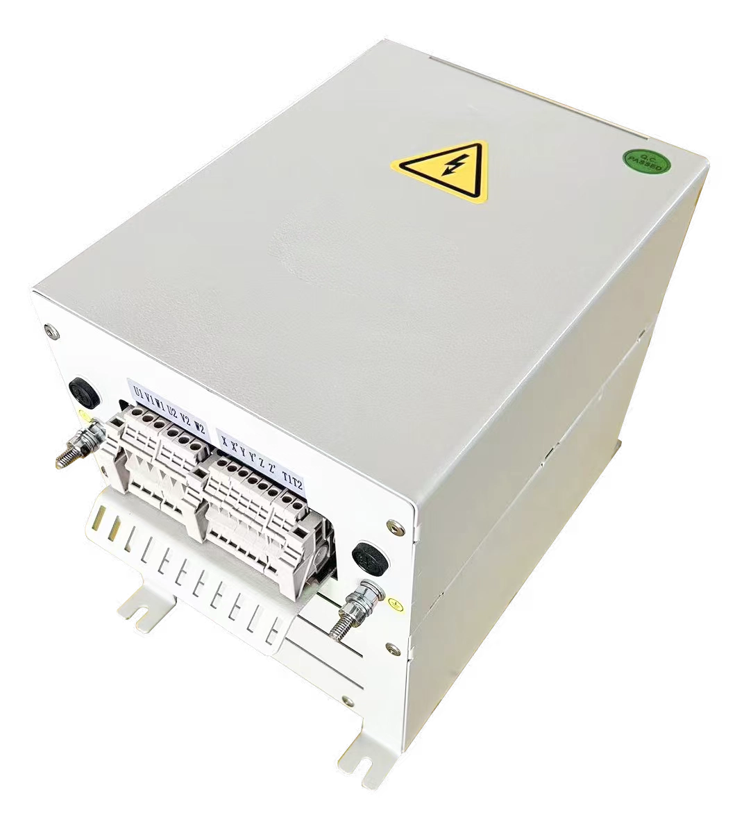
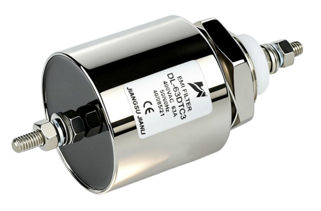
An input reactor is a series-connected AC inductor installed on the line-side of a VFD. It limits inrush current, attenuates harmonic distortion (THDi), and protects DC bus capacitors — essential in weak grids, multi-drive systems, and EMC-sensitive installations.
1. What Is an Input Reactor and How Does It Work?
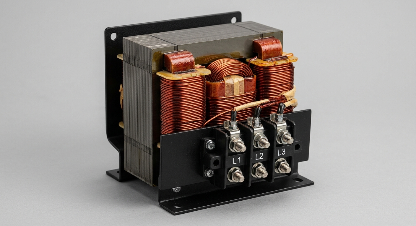
An input reactor for a VFD is a three-phase inductor inserted between the utility supply and the drive’s rectifier stage. Its core function is impedance insertion — typically 3% to 5% of the drive’s base impedance.
Operating mechanism:
- The inductor opposes rapid current change (V = L·dI/dt)
- Limits peak rectifier current during each AC cycle
- Smooths the pulsed current draw of the diode bridge
- Reduces voltage notching on the supply bus
Key electrical parameters:
| Parameter | Typical Range | Unit |
|---|---|---|
| Impedance (%Z) | 3% – 5% | Per-unit |
| Inductance | 0.5 mH – 5 mH | Millihenry |
| Current rating | 1 A – 2,000 A | Amperes |
| Voltage class | 200V / 400V / 690V | VAC |
| THDi reduction | 35% – 45% → 28% – 35% | Percentage |
A three phase input reactor operates symmetrically across all phases, ensuring balanced impedance insertion. Single-phase variants exist but are uncommon in industrial drives above 1 kW.
The inductor core material — silicon steel laminations or amorphous alloy — determines saturation current and thermal performance. Industrial-grade units use Class H (180°C) insulation minimum.
2. When Is an Input Reactor Required for a VFD?
Not every VFD installation mandates an input reactor. However, specific grid and load conditions make it technically necessary.
2.1 Weak Grid or High Source Impedance Conditions
- Grid short-circuit ratio (SCR) < 20 at the PCC
- Utility transformer rated below 10× the VFD kVA
- Long cable runs from transformer to drive (>30 m)
- Shared bus with large switching loads (welders, UPS)
Under weak grid conditions, voltage distortion at the point of common coupling (PCC) amplifies without series impedance. An input reactor for industrial drives adds controlled impedance that decouples the drive from supply fluctuations.
2.2 Multiple VFDs on a Common Bus
- Each drive’s rectifier draws non-sinusoidal current
- Harmonic currents from parallel drives accumulate
- Without reactors, THDi at PCC can exceed IEEE 519-2022 limits (typically 5% TDD at 69 kV–161 kV)
Rule of thumb: Install input reactors when total VFD load exceeds 30% of transformer kVA rating.
2.3 Sensitive Upstream Equipment
- Power factor correction (PFC) capacitor banks
- Precision CNC machines or medical imaging equipment
- Generators with limited fault current capacity
2.4 Long Motor Cable Installations
- Capacitive charging current from long cables stresses the rectifier
- Input reactor limits the transient charging spike at power-up
3. How a Three Phase Input Reactor Reduces VFD THDi
Harmonic distortion is the primary technical driver for deploying an industrial input reactor.
Mechanism of THDi reduction:
A standard 6-pulse VFD rectifier draws current in two pulses per half-cycle, generating characteristic harmonics at orders 6n±1 (5th, 7th, 11th, 13th…). The 5th harmonic alone can represent 25%–35% of fundamental current.
A three phase input reactor increases the commutation overlap angle (μ), spreading the current pulse over a wider time window:
- Wider pulse → lower peak-to-RMS ratio
- Reduced 5th and 7th harmonic amplitude
- Typical THDi reduction: from 80%–120% (no reactor) to 35%–45% (3% reactor) to 28%–35% (5% reactor)
THDi vs. Reactor Impedance:
| Reactor %Z | Typical THDi | 5th Harmonic (% fund.) | 7th Harmonic (% fund.) |
|---|---|---|---|
| None (0%) | 80% – 120% | 25% – 35% | 10% – 15% |
| 3% | 35% – 45% | 18% – 22% | 8% – 11% |
| 5% | 28% – 35% | 14% – 18% | 6% – 9% |
| 5% + 12-pulse | < 10% | < 3% | < 2% |
Source: IEEE 519-2022; ABB Technical Guide No. 6 (Harmonics in AC Drives)
For installations requiring THDi < 5% (IEEE 519 Category C), a custom input reactor combined with 12-pulse rectification or active front-end topology is required.
4. Input Reactor Selection Criteria: Impedance, Inductance, and Ratings
Selecting the correct VFD input reactor requires matching four interdependent parameters.
4.1 Impedance Rating (%Z)
- 3% impedance: Standard protection; balances harmonic reduction with voltage drop
- 5% impedance: Preferred for weak grids or high harmonic environments
- Higher than 5%: Increases voltage drop; rarely justified without active compensation
Voltage drop penalty: A 5% reactor at full load imposes ~5% fundamental voltage reduction. Verify motor voltage tolerance before specifying above 5%.
4.2 Inductance Value
Inductance (L) is derived from:
L = (%Z × V²) / (2π × f × kVA × 1000)
- For a 400V, 50Hz, 75 kW drive at 3%: L ≈ 0.68 mH
- For a 400V, 50Hz, 75 kW drive at 5%: L ≈ 1.14 mH
4.3 Continuous Current Rating
- Must equal or exceed VFD rated input current (not motor FLA)
- Add 10%–15% margin for harmonic current heating
- Verify with the input reactor supplier for derating at altitude >1,000 m or ambient >40°C
4.4 Saturation Current
- Must withstand inrush current (typically 6× to 10× rated current)
- Amorphous core material offers superior saturation performance vs. silicon steel
- Critical for input reactor manufacturer specification sheets
Selection Summary Table:
| Application | Recommended %Z | Core Type | Insulation Class |
|---|---|---|---|
| Standard industrial VFD | 3% | Silicon steel | Class F (155°C) |
| Weak grid / generator supply | 5% | Silicon steel | Class H (180°C) |
| High-cycle duty / harsh environment | 5% | Amorphous alloy | Class H (180°C) |
| EMC-critical / CE-marked installation | 5% + shielding | Amorphous alloy | Class H (180°C) |
5. Input Reactor vs. Line Reactor: Key Differences
The terms are frequently conflated. Technically:
- Input reactor: Installed on VFD line-side; optimized for rectifier harmonic mitigation
- Line reactor: Generic term; may refer to either line-side or load-side inductors
Under weak grid conditions, the distinction matters:
| Criterion | Input Reactor | DC Link Choke | Output Reactor |
|---|---|---|---|
| Placement | AC line-side | DC bus | Motor-side |
| THDi reduction | High (primary function) | Moderate | None |
| Capacitor bank protection | Yes | Yes | No |
| Motor cable protection | No | No | Yes |
| Voltage drop impact | Moderate | Low | Moderate |
An input reactor for variable frequency drive applications outperforms a DC link choke in THDi reduction but requires more physical space. For installations where panel space is constrained, DC bus chokes offer a compromise.
6. EMC Compliance and Custom Input Reactor Parameters
EMC compliance (IEC 61800-3, EN 55011) imposes conducted emission limits from 150 kHz to 30 MHz. Input reactors contribute to EMC performance through two mechanisms:
Differential-mode attenuation:
- Series inductance attenuates high-frequency switching noise propagating back to the supply
- Effective from ~10 kHz upward depending on self-resonant frequency (SRF)
Custom input reactor parameters for EMC compliance:
- Interwinding capacitance: Must be minimized (<50 pF) to preserve high-frequency attenuation
- Shielded enclosure: Electrostatic shield between primary winding and core reduces common-mode coupling
- Leakage inductance control: Tight tolerance (±5%) required for balanced three-phase attenuation
- SRF > 100 kHz: Ensures attenuation remains effective through VFD switching frequency harmonics
For CE-marked VFD systems, custom input reactor specifications must align with the drive manufacturer’s EMC filter design. Mismatched SRF between the reactor and EMC filter capacitors can create resonance peaks that worsen conducted emissions.
Standards Reference:
- IEC 61800-3:2017 (Adjustable speed drives — EMC requirements)
- EN 55011:2016+A1:2017 (Industrial, scientific, medical equipment)
- IEEE 519-2022 (Harmonic limits at PCC)
7. Real-World Application Scenarios
Scenario 1: Cement Plant Multi-Drive System
- 12× 75 kW VFDs on 1,600 kVA transformer
- Without reactors: THDi at PCC = 28% (exceeds IEEE 519 5% TDD limit)
- Solution: 5% three phase input reactor per drive
- Result: THDi reduced to 8%; transformer heating eliminated
Scenario 2: Offshore Platform Generator Supply
- 200 kW pump drive on 400 kVA diesel generator
- Generator SCR ≈ 8 (weak source)
- Solution: 5% industrial input reactor with Class H insulation
- Result: Voltage THD < 5%; generator governor instability resolved
Scenario 3: Food Processing EMC Compliance
- 15 kW conveyor VFD in CE-marked panel
- Conducted emissions failing EN 55011 Class A limits
- Solution: Custom input reactor with electrostatic shield + matched EMC filter
- Result: 12 dBμV conducted emission reduction; CE mark achieved
FAQ: Input Reactor for VFD — Technical Q&A
Q1: How does a three phase input reactor reduce VFD THDi?
By increasing commutation overlap angle, spreading current pulses and reducing 5th/7th harmonic amplitude by 30%–50%.
Q2: What impedance rating criteria govern industrial input reactor selection?
3% for standard grids; 5% for weak grids or generator supplies; verify voltage drop tolerance.
Q3: How does input reactor inductance mitigate VFD capacitor bank stress?
Series inductance limits dV/dt and peak charging current, reducing capacitor ripple current by 40%–60%.
Q4: How do input reactors compare to line reactors under weak grid conditions?
Input reactors provide superior THDi reduction; line reactors are generic terms covering both placements.
Q5: What custom input reactor parameters address EMC compliance in VFD installations?
Minimize interwinding capacitance (<50 pF), add electrostatic shielding, control SRF >100 kHz.
Q6: When is a 5% reactor preferred over 3%?
When grid SCR < 20, generator supply, or IEEE 519 compliance requires THDi < 35%.
Q7: Can an input reactor replace an EMC filter?
No. It attenuates differential-mode harmonics but does not replace common-mode EMC filters.
Q8: What is the typical voltage drop across a 5% input reactor at full load?
Approximately 4%–5% of supply voltage; verify motor nameplate voltage tolerance.
Conclusion
An input reactor for a VFD is not optional in weak grid environments, multi-drive installations, or EMC-regulated applications. The technical case is clear:
- 3% impedance reactors reduce THDi from 80%–120% to 35%–45%
- 5% impedance reactors are required for generator supplies and IEEE 519 compliance
- Custom input reactor designs with controlled SRF and electrostatic shielding are mandatory for IEC 61800-3 EMC compliance
- Selection must account for continuous current rating, saturation current, insulation class, and altitude derating
For procurement teams and systems integrators, engaging a qualified input reactor manufacturer or input reactor supplier with documented test data per IEC 60076-6 (reactors standard) ensures both performance and regulatory compliance.
Specify the reactor before the drive installation — retrofitting costs 3×–5× more than upfront integration.
References and Standards
- IEEE 519-2022 — Recommended Practice and Requirements for Harmonic Control in Electric Power Systems
- IEC 61800-3:2017 — Adjustable Speed Electrical Power Drive Systems — EMC Requirements
- IEC 60076-6:2007 — Power Transformers — Part 6: Reactors
- EN 55011:2016+A1:2017 — Industrial, Scientific and Medical Equipment — Radio-Frequency Disturbance Characteristics
- ABB Technical Guide No. 6 — Guide to Harmonics with AC Drives (ABB Oy, 2017)
- Mohan, Undeland & Robbins — Power Electronics: Converters, Applications, and Design, 3rd Ed. (Wiley, 2002)
- Bollen, M.H.J. — Understanding Power Quality Problems (IEEE Press, 2000)