
Abstract
Variable Frequency Drives have transformed industrial motor control, delivering significant energy savings across pump, fan, compressor, and conveyor applications. However, their inherent operating principle—converting AC to DC through a rectifier bridge before synthesizing variable-frequency output—introduces substantial harmonic distortion into the upstream power system. Left unmitigated, these harmonics elevate Total Harmonic Distortion of current (THDi), degrade power quality, overheat transformers, and trigger nuisance tripping of protective devices.
The Input Reactor is one of the most cost-effective and widely deployed harmonic mitigation devices available to facilities engineers and procurement specialists. By inserting a series inductance between the utility supply and the VFD’s DC bus capacitors, the reactor limits the rate of current change, attenuates characteristic harmonic orders, and reduces peak rectifier currents. This article provides a technically grounded evaluation of how Input Reactors function, what performance to expect at 3% versus 5% impedance ratings, which compliance standards govern their application, and how they compare commercially to active filtering alternatives.
1. How Input Reactors Limit Harmonic Currents in VFD Systems
1.1 The Root Cause of VFD-Generated Harmonics
A standard six-pulse VFD draws current through a diode rectifier bridge that conducts only during the peaks of each voltage half-cycle. Unlike a linear load—such as a resistive heater or induction motor running directly on line—this non-linear load draws current in short, high-amplitude pulses rather than a smooth sinusoidal waveform. Fourier analysis of this pulsed waveform reveals dominant harmonic components at the 5th, 7th, 11th, and 13th harmonic orders (characteristic harmonics of a six-pulse topology), with THDi values frequently ranging from 80% to over 120% at the VFD input terminals under light-load or low-impedance source conditions.
The consequences propagate upstream: harmonic currents flowing through source impedance create harmonic voltages that distort the Point of Common Coupling (PCC) waveform, affecting all equipment sharing the same bus. Transformers experience additional eddy-current losses; capacitor banks may resonate; sensitive instrumentation and programmable logic controllers can malfunction. Quantifying and mitigating this distortion is therefore both a power quality obligation and an operational reliability requirement.
1.2 Impedance as a Harmonic Barrier: The Reactor’s Working Principle
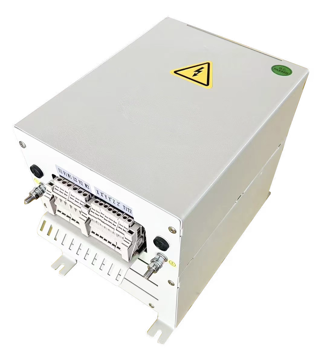
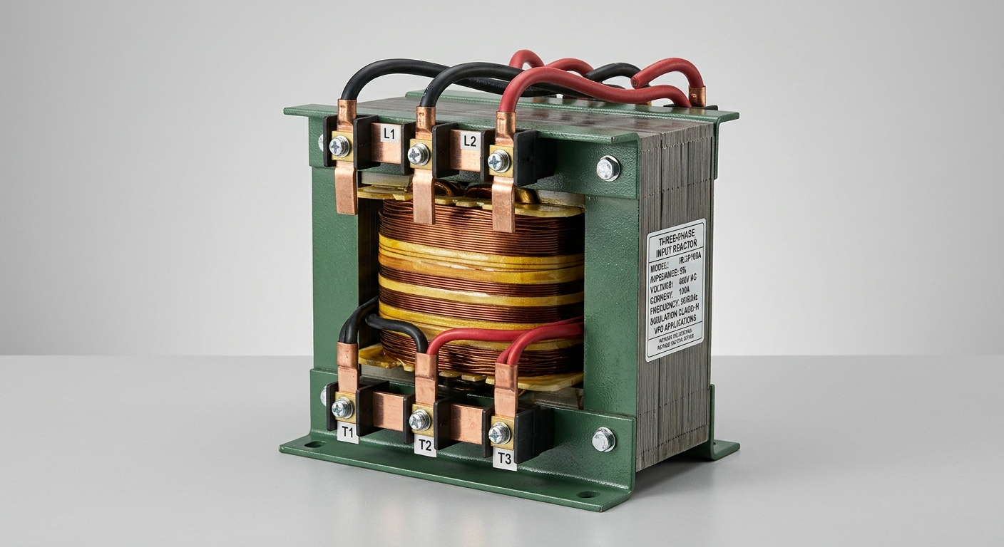
An Input Reactor is a three-phase series inductor installed on the line-side terminals of the VFD. Its fundamental action is governed by Faraday’s law: voltage across an inductor equals L × (di/dt), meaning the reactor opposes rapid changes in current. By inserting sufficient inductance, the reactor:
- Limits peak rectifier current, broadening the conduction angle from the narrow pulses of an unimpeded rectifier to a wider, lower-amplitude waveform.
- Attenuates harmonic current amplitude at the 5th and 7th orders, where the majority of distortion energy resides in six-pulse drives.
- Reduces DC bus capacitor charging stress, extending capacitor service life as a secondary benefit.
The impedance presented by the reactor at each harmonic frequency scales linearly with frequency (Z = 2πfL), meaning higher-order harmonics face proportionally greater opposition. A reactor rated at 3% impedance on the fundamental reduces 5th harmonic current by approximately 15–20%, while a 5% reactor achieves reductions in the 35–40% range under typical source conditions—translating to system THDi values dropping from the 80–120% unmitigated range down to 35–50% with a 3% unit, and 28–40% with a 5% unit.
2. Key Factors That Affect Input Reactor Performance
2.1 Impedance Rating Selection: 3% vs. 5%
Impedance percentage is defined relative to the VFD’s rated kVA base: a 5% reactor drops 5% of nominal voltage at full rated current. Selecting between 3% and 5% involves balancing harmonic attenuation against fundamental voltage drop and the resulting impact on motor terminal voltage.
| Parameter | 3% Impedance Reactor | 5% Impedance Reactor |
|---|---|---|
| Typical THDi Reduction | 35–50% (absolute) | 50–70% (absolute) |
| Fundamental Voltage Drop | ~2.5–3% at full load | ~4–5% at full load |
| Applicable VFD Range | 0.75 kW – 500 kW (11 HP – 670 HP) | 0.75 kW – 500 kW (11 HP – 670 HP) |
| Resulting System THDi | 35–50% | 28–40% |
| Recommended Scenario | Stiff grid (high SCR), cost-sensitive retrofit, IEEE 519 compliance with transformer impedance support | Weak grid (low SCR), dedicated transformer, sensitive shared bus, tight compliance margin |
For facilities where the supply transformer already contributes 4–5% impedance, a 3% reactor may deliver adequate combined impedance. Where the VFD is fed from a dedicated low-impedance source or large transformer, a 5% reactor compensates for the missing natural source impedance.
2.2 System Source Impedance and Installation Environment
The Short Circuit Ratio (SCR)—the ratio of available fault current to VFD rated current—directly governs how much harmonic current the supply can absorb before voltage distortion becomes significant. High-SCR (stiff) systems have low source impedance; harmonic currents flow freely and distort the voltage waveform less. Low-SCR (weak) systems amplify voltage distortion from the same harmonic current magnitude.
When multiple VFDs share a common bus, individual reactor performance is cumulative but not simply additive. Each reactor limits its own drive’s harmonic injection; however, harmonic currents from different drives can interact through shared bus impedance. In multi-drive installations, per-drive reactors remain the preferred architecture over a single bus reactor, as they provide fault current protection and ride-through benefits to each individual drive in addition to harmonic mitigation.
3. Compliance Standards and Harmonic Distortion Benchmarks
3.1 IEEE 519 and IEC 61000 Requirements for Industrial Sites
IEEE 519-2022 establishes current distortion limits at the PCC based on the ISC/IL ratio (short-circuit current to maximum demand load current). For most industrial facilities with ISC/IL ratios between 20 and 50—the most common range—the standard limits individual harmonic orders to 4–7% and Total Demand Distortion (TDD) to 8%. Critically, IEEE 519-2022 measures compliance at the PCC (typically the utility metering point), not at individual equipment terminals.
IEC 61000-3-12 applies to equipment with input current up to 75 A per phase connected to public low-voltage networks, specifying harmonic current emission limits based on the short-circuit ratio at the connection point. For industrial sites with dedicated medium-voltage connections, IEC 61000-3-4 provides the relevant framework, requiring site-level harmonic assessments.
Compliance obligations are typically triggered by utility contracts, new equipment commissioning audits, or documented power quality complaints from neighboring facilities sharing the same distribution transformer.
3.2 When an Input Reactor Is Sufficient vs. When to Upgrade
An Input Reactor is generally sufficient when:
- The facility’s baseline THDi, after reactor installation, falls within IEEE 519 TDD limits at the PCC.
- The combined source-plus-reactor impedance reaches 5–8% of the VFD’s kVA base.
- The load profile is relatively stable (not highly variable or regenerative).
When an Input Reactor alone cannot achieve compliance—typically in large VFD installations exceeding 30–40% of transformer capacity, or on very weak grids—the escalation path includes Active Power Filters (APF), which inject compensating harmonic currents in real time and can reduce THDi below 5%, and 12-pulse or 18-pulse rectifier configurations, which cancel characteristic harmonic orders through phase-shifted transformer windings. Both alternatives cost 3–8× more than a passive reactor solution and are justified only when compliance margins or operational sensitivity demands it.
4. Application Scenarios and Commercial Value for Procurement Engineers
4.1 Typical Industrial Use Cases
Input Reactors deliver the highest value in the following deployment scenarios:
- Pump and fan drives: HVAC, water treatment, and process cooling systems where VFDs operate at variable load and share distribution panels with sensitive instrumentation or PLC systems.
- Compressor drives: Constant-torque loads with high inrush during start cycles, where reactor current-limiting also reduces mechanical stress on the drivetrain.
- Retrofit projects: Facilities adding VFDs to existing fixed-speed motor circuits, where the existing transformer and wiring were not sized for harmonic loads. A reactor is the lowest-disruption upgrade path.
- Shared bus protection: Manufacturing cells where precision CNC equipment, servo drives, or medical imaging systems share the same electrical distribution as VFD-driven auxiliary equipment.
4.2 Total Cost of Ownership: Input Reactor vs. Alternative Mitigation Methods
From a procurement perspective, the Input Reactor’s value proposition centers on its favorable TCO across the mitigation spectrum:
| Cost Factor | Input Reactor | Active Power Filter | 12-Pulse Drive |
|---|---|---|---|
| Initial Capital Cost | Low (5–15% of VFD cost) | High (50–150% of VFD cost) | Medium (20–40% premium) |
| Installation Complexity | Minimal (series connection) | Moderate (CT sensing, commissioning) | High (phase-shift transformer) |
| Ongoing Maintenance | None (passive device) | Annual filter capacitor inspection | Transformer maintenance |
| Power Loss | 0.5–1.5% of rated load | 1–2% (filter losses) | 0.3–0.8% |
| Harmonic Performance | Moderate (THDi 28–50%) | Excellent (THDi <5%) | Good (THDi 8–15%) |
| Payback Period | Immediate (avoided penalties) | 3–7 years | 2–5 years |
For the majority of industrial VFD applications where IEEE 519 compliance is achievable with moderate harmonic reduction, the Input Reactor delivers the optimal balance of performance, simplicity, and cost.
FAQ
1. What percentage of THD reduction can I realistically expect from a 5% input reactor on my VFD system?
A 5% impedance Input Reactor typically reduces system THDi by 50–70% relative to the unmitigated baseline. On a standard six-pulse VFD with no source impedance, THDi may drop from 90–120% down to 28–40%. Actual results depend on source SCR, load percentage, and whether additional impedance exists in the supply transformer.
2. Can a single input reactor protect multiple VFDs connected to the same bus?
A single bus-level reactor provides some attenuation for all downstream drives but is less effective than per-drive reactors. It also does not provide individual drive protection against fault currents or voltage transients. Per-drive installation is the industry-recommended practice for both harmonic mitigation and equipment protection.
3. Will adding an input reactor cause a noticeable voltage drop that affects motor performance?
At full load, a 5% reactor introduces approximately 4–5% fundamental voltage drop. In most applications, this is compensated by the VFD’s output voltage boost function. However, for motors already operating near their voltage tolerance limits, a 3% reactor (2.5–3% drop) may be preferable, or the supply voltage should be verified to provide adequate headroom.
Conclusion
The Input Reactor remains a proven, cost-effective first line of defense against VFD-generated harmonic distortion. Its passive series-impedance design requires no active components, no commissioning software, and no ongoing maintenance—making it the lowest-risk harmonic mitigation solution available to facility engineers and procurement teams. Selecting between 3% and 5% impedance should be guided by a structured assessment of source SCR, transformer capacity, load profile, and the applicable compliance standard—whether IEEE 519-2022 or IEC 61000-3-12. For the large majority of industrial VFD installations, a correctly rated Input Reactor achieves compliant harmonic levels at a fraction of the cost of active filtering or multi-pulse alternatives, delivering an immediate return through avoided utility penalties, reduced equipment stress, and extended service life across the connected electrical system.