
Abstract
Feedthrough filters are critical passive components in EMI shielding systems, enabling signal or power lines to pass through shielded enclosures while suppressing unwanted high-frequency noise. Unlike surface-mount capacitors or standalone filter modules, feedthrough filters are uniquely designed to mount directly into a conductive panel wall — making them an integral part of the shielding boundary itself.
This article explains how feedthrough filters work, defines key technical parameters such as insertion loss and self-resonant frequency, and provides structured selection criteria covering electrical, mechanical, and compliance requirements. Whether you are designing a shielded military enclosure, an industrial motor drive cabinet, or a medical device chassis, understanding how feedthrough filters work—and how to specify them correctly—is essential to achieving predictable, regulation-compliant EMC performance.
1. What Is a Feedthrough Filter?
1.1 Definition and Core Function
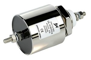
A feedthrough filter is a two-port passive EMI suppression component designed to be mounted through a conductive panel or enclosure wall. One terminal connects to the external (noisy) side of the circuit, and the other connects to the protected interior. The enclosure wall itself serves as the ground reference point.
This through-panel mounting architecture is what fundamentally distinguishes a feedthrough filter from a standard PCB-mounted capacitor or a chassis-mounted EMI filter module. A PCB capacitor routes noise current back through the PCB ground plane — a path that may carry significant impedance at high frequencies. A feedthrough filter, by contrast, diverts noise current directly to the shielded enclosure wall at the point of entry, maintaining the integrity of the shielding boundary. This direct bonding to the panel is the key mechanism that enables the filter to perform as part of a complete Faraday cage system rather than as an isolated circuit element.
The core function is low-pass filtering: DC and low-frequency signals pass through with minimal attenuation, while high-frequency interference — whether conducted onto power lines or signal cables from external sources — is shunted to ground before it can enter or exit the shielded enclosure.
1.2 Common Types and Configurations
Feedthrough filters are available in three primary topologies, each offering a different balance between simplicity and suppression performance:
- C-type (Capacitor-only): A single capacitor element between the signal conductor and ground. Effective for broadband HF suppression in low-impedance source applications. Simple, compact, and cost-effective.
- LC-type: Combines a series inductor with a shunt capacitor. Provides steeper roll-off above the cutoff frequency and better performance in medium-impedance circuits.
- π-type (Pi-filter): Two shunt capacitors flanking a series inductor. Delivers the highest insertion loss across a broad frequency range and is preferred in demanding military and industrial applications.
Beyond topology, feedthrough filters are available in single-line and multi-line configurations — from single-conductor threaded feedthroughs to multi-pin array versions for connector panels. Mounting styles include solder-in (for PCB integration at the panel edge), threaded stud (for panel hole mounting with nut retention), and press-fit variants for high-volume production.
2. How Does a Feedthrough Filter Work in EMI Shielding?
2.1 Working Principle: Signal Path and Noise Suppression Mechanism
The feedthrough filter operates on the principle of frequency-selective impedance. At low frequencies — including DC, audio, and fundamental power frequencies — the filter presents low impedance in the signal path and high impedance to ground, allowing the intended signal to pass with negligible loss.
At high frequencies, the behavior reverses. The shunt capacitor(s) present low impedance to ground, diverting HF noise current away from the protected circuit and into the enclosure wall. In LC and π configurations, the series inductor simultaneously presents high impedance to HF noise in the signal path, reinforcing the blocking effect.
Critically, the noise current is not simply dissipated — it is returned to the shielded enclosure structure. This is why the mechanical bond between the filter body and the panel is as important as the electrical component values. A poor mechanical connection (e.g., loose thread, painted panel surface, inadequate torque) introduces contact impedance that degrades shielding effectiveness at the point of entry, undermining the entire enclosure’s EMC performance.
The result is that conducted EMI — whether entering from an external power supply or radiating from an internal switching circuit — is intercepted at the enclosure boundary rather than allowed to propagate freely.
2.2 Insertion Loss and Frequency Response
Insertion loss (IL), measured in decibels, is the primary performance metric for feedthrough filters. It quantifies the reduction in signal power at a given frequency when the filter is inserted into the circuit. Higher insertion loss values indicate greater noise suppression.
Key frequency-domain parameters include:
- Cutoff frequency (f₋₃dB): The frequency at which insertion loss reaches 3 dB — effectively defining the boundary between the passband and the stopband.
- Self-resonant frequency (SRF): Above this frequency, parasitic inductance in the capacitor causes insertion loss to decrease. Selecting a filter with an SRF well above the target interference band is essential.
- Insertion loss at reference frequencies: Specifications typically quote IL at 10 MHz, 100 MHz, and 1 GHz to characterize broadband performance.
| Filter Type | Capacitance Range | Rated Voltage | IL @ 100 MHz (Typical) | Effective Frequency Range | Mounting Style | Operating Temp |
|---|---|---|---|---|---|---|
| C-type | 100 pF – 10 µF | 50 V – 500 V DC/AC | 20 – 40 dB | 1 MHz – 1 GHz | Threaded / Solder-in | -55°C to +125°C |
| LC-type | 1 nF – 1 µF | 50 V – 250 V DC | 40 – 60 dB | 100 kHz – 1 GHz | Threaded / Press-fit | -55°C to +125°C |
| π-type | 1 nF – 470 nF | 50 V – 500 V DC/AC | 60 – 80 dB | 10 kHz – 1 GHz | Threaded / Solder-in | -55°C to +125°C |
3. Key Selection Criteria for EMI Suppression Applications
3.1 Electrical Parameters and Shielding Effectiveness Requirements
Selecting the correct feedthrough filter begins with defining the target interference frequency and the required insertion loss at that frequency. As a practical starting point, the required capacitance value can be estimated from the target suppression frequency using the relation f = 1/(2πRC), where R is the source or load impedance.
Beyond capacitance, the following electrical parameters require careful verification:
- Rated current: Feedthrough filters carry the full line current. Thermal derating must be applied at elevated operating temperatures — typically reducing the rated current by 20–30% at 85°C.
- Rated voltage: Both DC and AC ratings must exceed the maximum system voltage with appropriate margin. Surge and transient voltage conditions should also be evaluated.
- Leakage current: In medical and safety-critical applications, the capacitance value directly determines leakage current to ground. IEC 60601-1 imposes strict limits that constrain maximum capacitance on patient-connected circuits.
- Enclosure continuity: No filter specification compensates for a poorly bonded panel. The enclosure must provide a low-impedance ground path from the filter mounting point throughout the shielded structure.
3.2 Mechanical and Environmental Compliance Standards
Feedthrough filters intended for professional and regulated applications must conform to recognized test and compliance standards:
- MIL-STD-220: The primary insertion loss test method for feedthrough filters, specifying 50 Ω source and load impedances. Performance data quoted per MIL-STD-220 allows direct comparison between suppliers.
- IEC 61000-4 series: Defines immunity test levels for conducted and radiated interference, providing the system-level context within which the filter must perform.
- RoHS / REACH compliance: Required for commercial and consumer market access in the EU and increasingly mandated in industrial procurement specifications globally.
Mechanical considerations include panel thickness compatibility (threaded feedthroughs are available in multiple thread lengths), torque specifications for proper panel bonding, and body material — typically brass with tin or nickel plating for corrosion resistance. For harsh industrial and outdoor environments, confirm operating temperature range (typically -55°C to +125°C for military-grade components) and resistance to humidity, vibration, and chemical exposure per applicable qualification standards.
4. Typical Application Scenarios and Industry Use Cases
4.1 Industrial and Defense Electronics
In shielded equipment cabinets for industrial automation, feedthrough filters are installed at every power entry point — including AC mains, DC bus lines, and control signal cables — to prevent switching noise from variable frequency drives and inverters from propagating into sensitive measurement or communication circuits.
In avionics and military electronics, feedthrough filters are mandatory at all enclosure penetrations. MIL-STD-461 compliance for conducted emissions and susceptibility (CE102, CS101) directly depends on the insertion loss performance of feedthrough filters at power entry points. π-type configurations with insertion loss exceeding 60 dB at 1 MHz are standard in these environments. The ruggedized construction — hermetically sealed, high-temperature rated, and vibration-resistant — ensures reliability under extreme operational conditions.
Motor drive and power inverter applications benefit from LC and π-type feedthrough filters to suppress the broadband conducted noise generated by high-frequency PWM switching, protecting co-located communication interfaces and sensor circuits.
4.2 Medical, Telecom, and Commercial Equipment
Medical devices must comply with IEC 60601-1-2 for electromagnetic compatibility. Feedthrough filters on power entry lines and signal interfaces help achieve the required immunity levels while controlling emissions — but capacitance selection must account for leakage current limits, particularly for equipment in direct patient contact.
Telecom base stations and radio equipment use feedthrough filters extensively on DC power feeds entering shielded RF compartments, preventing low-frequency power supply noise from coupling into sensitive receiver chains. Data center rack-mount equipment applies feedthrough filtering on power distribution units and management interfaces to meet CISPR 32 emissions limits.
FAQ
1. What is the difference between a feedthrough filter and a standard EMI filter module?
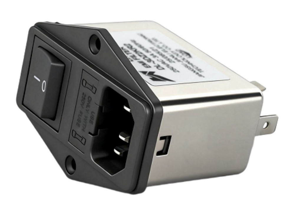
A standard EMI filter module is a multi-element assembly (typically IEC inlet or terminal block format) designed for power line filtering at the equipment level. A feedthrough filter is a single-line component that mounts directly through a conductive panel, making it part of the shielding boundary. Feedthrough filters are used where individual line-by-line filtering at the enclosure wall is required — particularly in high-shielding-effectiveness enclosures where any unfiltered penetration would compromise the entire shield.
2. How do I select the correct capacitance value for my target interference frequency?
Use the low-pass cutoff formula: f = 1/(2πRC), where R is the impedance of the source or load (typically 50 Ω for RF, or the actual line impedance for power applications). For a target suppression frequency of 10 MHz with 50 Ω impedance, a capacitance of approximately 300 pF is a starting point. Verify against measured insertion loss data across the full frequency range of concern.
3. Can feedthrough filters be used on both power lines and signal lines simultaneously?
Yes. Multi-line feedthrough filter arrays are available for simultaneous filtering of multiple conductors — including mixed power and signal lines — through a single panel aperture. Each line is independently filtered. Ensure that the capacitance value and current rating are appropriate for each conductor, as power and signal lines typically require different filter specifications.
Conclusion
Feedthrough filters serve as a foundational element in achieving reliable EMI shielding across industrial, defense, medical, and commercial applications. Their through-panel mounting architecture makes them uniquely effective: by grounding noise current directly at the enclosure boundary, they preserve shielding integrity in a way that no PCB-mounted component can replicate.
Selecting the correct feedthrough filter requires aligning insertion loss performance with target frequency bands, matching electrical ratings to actual operating conditions with appropriate derating, and verifying compliance with applicable standards such as MIL-STD-220, IEC 61000-4, and RoHS. Mechanical integration — particularly the quality of the panel bond — is as critical as the component specification itself.
Engineers who treat the feedthrough filter as part of the system-level shielding architecture, rather than an afterthought, will achieve more consistent and compliant EMC performance from first build to final certification.