
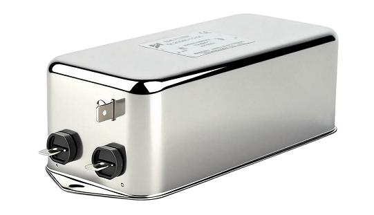
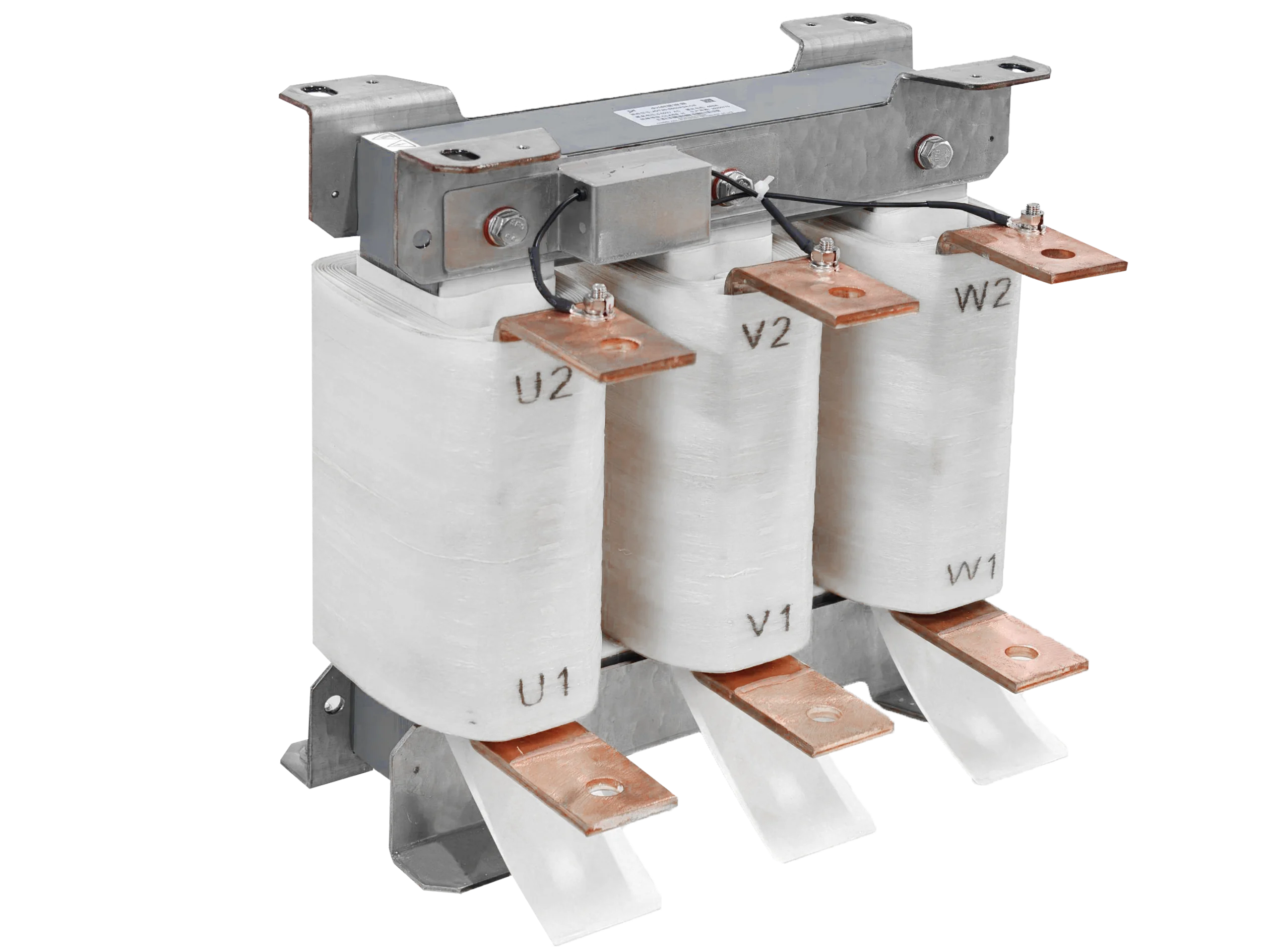
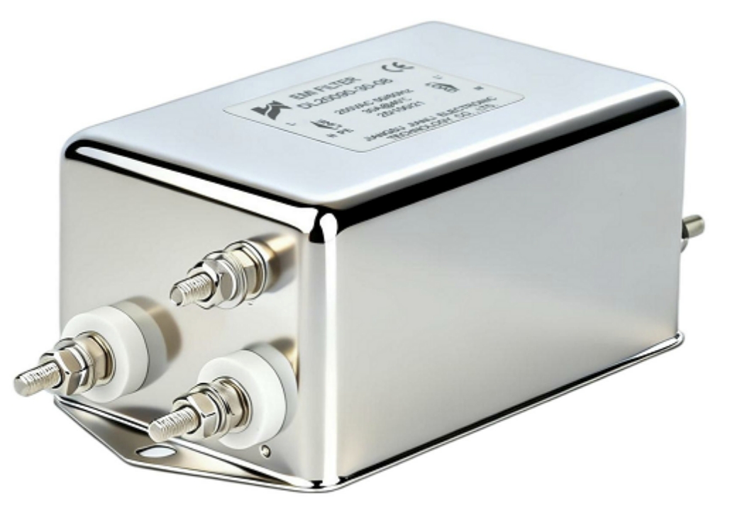
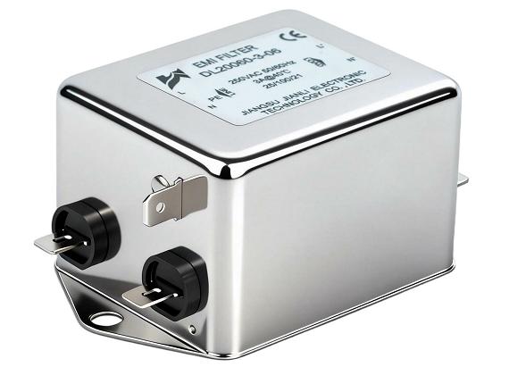
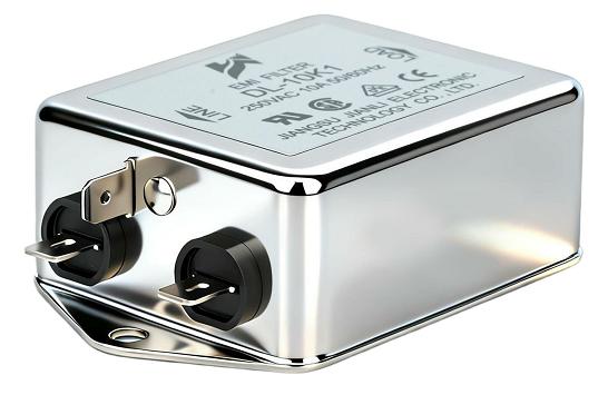
A feedthrough filter is a two-terminal EMI suppression component mounted directly in a conductive panel, providing low-impedance grounding for high-frequency noise while maintaining DC/low-frequency signal continuity. It achieves superior insertion loss compared to standard bypass capacitors by eliminating lead inductance through direct chassis bonding.
What Is the Main Purpose of a Feedthrough Filter?
A feedthrough filter serves one primary function: intercept conducted EMI on signal or power lines before it propagates into or out of a shielded enclosure.
- Blocks RF noise in the range of 1 MHz to 10 GHz
- Maintains signal integrity for DC and low-frequency operational currents
- Provides a direct, low-inductance path to chassis ground
- Complies with IEC 61000-4-6, MIL-STD-461, and CISPR 22 conducted emission limits
Why it matters: Every unfiltered conductor penetrating a shielded enclosure acts as an antenna. A feedthrough filter seals that aperture electromagnetically while keeping the circuit functional.
| Parameter | Typical Value Range |
|---|---|
| Frequency Range | 1 MHz – 10 GHz |
| Capacitance Range | 100 pF – 100 nF |
| Rated Voltage | 50 V – 2,500 V DC |
| Rated Current | 0.5 A – 30 A |
| Insertion Loss (at 100 MHz) | 20 dB – 60 dB |
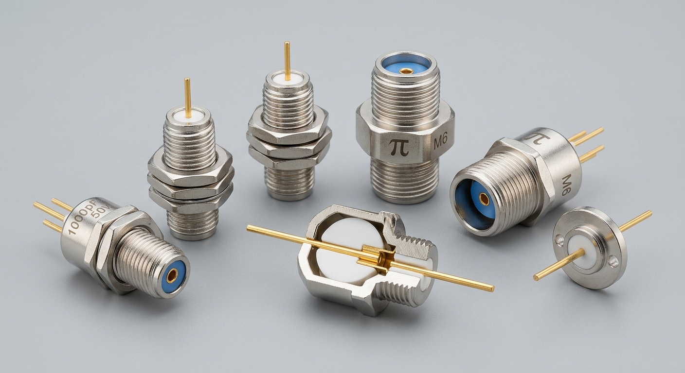
How Does a Feedthrough Filter Reduce High-Frequency EMI?
The Core Operating Mechanism
A feedthrough filter operates as a low-pass filter integrated into a conductive barrier.
- The capacitor element shunts high-frequency currents directly to the chassis
- The inductive element (in LC or π-type designs) blocks RF from passing through
- Together, they form a frequency-selective network: transparent below cutoff, attenuating above it
Cutoff frequency formula:
f_c = 1 / (2π√LC)
For a 1 nF capacitor with 10 nH lead inductance, f_c ≈ 50 MHz — typical for industrial power line filtering.
Why Lead Inductance Is the Critical Differentiator
Standard bypass capacitors suffer from parasitic lead inductance (5–20 nH), which degrades performance above 100 MHz. A feedthrough filter eliminates this by:
- Mounting the capacitor body directly in the panel aperture
- Creating a zero-lead-length ground connection via the threaded or flange mount
- Achieving effective feedthrough filter insertion loss of 40–60 dB at 1 GHz vs. 10–20 dB for leaded capacitors
Filter Topology Comparison
| Topology | Configuration | Best Use Case | Insertion Loss Profile |
|---|---|---|---|
| C-type | Single capacitor | Low-cost signal lines | Moderate, <500 MHz |
| LC-type | Inductor + capacitor | Power lines with moderate noise | Good, up to 1 GHz |
| π-type | C-L-C | High-interference environments | Excellent, up to 10 GHz |
| T-type | L-C-L | High source/load impedance | High, broadband |
What Is the Difference Between a Feedthrough Filter and a Standard EMI Filter?
Structural Distinction
| Feature | Feedthrough Filter | Standard EMI Filter (Panel-Mount Box) |
|---|---|---|
| Mounting | Direct chassis penetration | External enclosure, bolted to panel |
| Ground Path | Zero-inductance via metal body | Via wire/strap (adds 5–50 nH) |
| Form Factor | Single conductor, compact | Multi-conductor, bulky |
| Frequency Effectiveness | Up to 10 GHz | Typically up to 1–3 GHz |
| Cost per Line | Low ($0.50–$15) | Higher ($10–$200+) |
| Installation Complexity | Moderate (requires panel drilling) | Lower (external mount) |
When to Choose Each
Use a feedthrough filter when:
- A single conductor must penetrate a shielded enclosure
- Space constraints prohibit external filter housings
- Frequencies above 1 GHz must be attenuated
- MIL-SPEC or aerospace shielding integrity is required
Use a standard EMI filter when:
- Multiple lines (AC mains + neutral + ground) need simultaneous filtering
- The enclosure is not a primary Faraday shield
- Installation access is limited to external surfaces
The key distinction: a feedthrough filter is a shielding component as much as a filtering component. Its value lies in maintaining enclosure integrity, not just attenuating noise.
How Do You Choose the Right Feedthrough Filter for an Industrial Application?
Applying feedthrough filter selection criteria requires evaluating five parameters systematically.
Step 1 — Define the Frequency Range
- Identify the dominant interference frequencies (conducted emissions scan per CISPR 32)
- For switching power supplies: focus on 150 kHz – 30 MHz
- For RF-dense environments (5G, radar): extend to 1–10 GHz
- Match the feedthrough filter frequency range to the measured interference spectrum
Step 2 — Determine Current and Voltage Rating
- Derate rated current by 20–30% for thermal margin in enclosed installations
- For high-voltage industrial DC buses (400–800 V), select filters rated ≥1,000 V DC
- Check ripple current rating for capacitor types in switching applications
Step 3 — Select Capacitance and Topology
- Low-impedance sources (power rails): use π-type for maximum attenuation
- High-impedance signal lines: C-type or LC-type to avoid signal distortion
- Capacitance above 10 nF may cause excessive reactive current on AC lines
Step 4 — Evaluate Mechanical and Environmental Requirements
- Thread size standards: M3, M4, M5, M6, 1/4-28 UNF (military)
- Operating temperature: –55°C to +125°C (military grade); –25°C to +85°C (industrial)
- IP rating of the panel assembly must account for the filter aperture seal
- For MIL-STD-461 compliance, select MIL-C-11015 or MIL-PRF-28861 qualified parts
Step 5 — Verify Insertion Loss Requirements
- Specify minimum insertion loss (dB) at target frequencies
- Request measured data per MIL-STD-220 or IEC 60939 test methods
- Industrial feedthrough EMI filter datasheets should show insertion loss curves, not just single-frequency values
Does Feedthrough Filter Installation Affect EMI Suppression Performance?
Yes — installation quality directly determines whether rated insertion loss is achieved in practice.
Critical Installation Factors
Panel bonding integrity:
- The filter body must make 360° metal-to-metal contact with the panel
- Surface finish must be bare metal (no paint, anodizing, or oxide layer) at the contact ring
- Poor bonding adds 10–30 nH of parasitic inductance, reducing high-frequency performance by 20–40 dB
Panel thickness compatibility:
- Thread engagement must be ≥1.5× thread diameter
- For thin panels (<1.5 mm), use flange-mount or solder-in styles
Lead dress on the protected side:
- Filtered leads must be physically separated from unfiltered leads
- Mixing filtered and unfiltered wiring on the same side can couple noise back, negating 15–25 dB of insertion loss
Common installation errors:
- Applying conductive grease incorrectly (use only on mating surfaces, not threads)
- Over-torquing ceramic feedthrough filters (causes capacitor cracking; max torque typically 0.5–1.5 N·m)
- Installing filters in non-conductive panels without a metal ground washer assembly
Real-World Application Scenarios
Scenario 1 — Industrial Motor Drive Enclosure
A 22 kW VFD generates conducted emissions at 2–20 MHz. π-type feedthrough filters rated 10 A / 630 V DC are installed on all control signal lines entering the enclosure. Result: 35 dB reduction in radiated emissions, achieving CISPR 11 Class A compliance.
Scenario 2 — Military Communications Equipment
MIL-STD-461G CS114/RE102 requirements demand >60 dB insertion loss at 400 MHz. MIL-PRF-28861 qualified feedthrough filters (T-type, 1,000 pF, 5 A) are installed on all DC power penetrations. Enclosure shielding effectiveness is maintained at 80 dB.
Scenario 3 — Medical Imaging Device Power Supply
IEC 60601-1-2 EMC compliance requires conducted emission suppression on 48 V DC input lines. LC-type feedthrough filters (4.7 nF, 8 A) reduce common-mode noise by 28 dB across 150 kHz–30 MHz, meeting IEC 61000-6-2 immunity requirements.
FAQ: Feedthrough Filters for EMI/RFI Suppression
Q: What is the main purpose of a feedthrough filter?
To block high-frequency EMI on conductors passing through a shielded enclosure wall.
Q: What feedthrough filter frequency range is typical?
1 MHz to 10 GHz, depending on capacitance and topology.
Q: How does feedthrough filter insertion loss compare to bypass capacitors?
40–60 dB vs. 10–20 dB at 1 GHz due to zero lead inductance.
Q: What is the difference between a feedthrough filter and a bypass capacitor?
A feedthrough filter mounts in the panel itself; a bypass capacitor uses leads that add parasitic inductance.
Q: Can feedthrough filters be used on AC power lines?
Yes, with capacitance values ≤10 nF to limit reactive current and leakage.
Q: What standards govern feedthrough filter testing?
MIL-STD-220, IEC 60939, and MIL-PRF-28861 are primary qualification standards.
Q: What causes feedthrough filter performance degradation after installation?
Poor panel bonding, mixed filtered/unfiltered wiring, and mechanical damage to the ceramic element.
Q: How do I select feedthrough filter capacitance for a 10 MHz interference problem?
Use 1–10 nF capacitance to achieve the required cutoff frequency below 10 MHz.
Conclusion and Engineering Recommendations
Feedthrough filters are the highest-performance single-component solution for EMI suppression at enclosure penetration points. Their zero-lead-length chassis ground connection delivers insertion loss levels unachievable by leaded alternatives, particularly above 100 MHz.
Key engineering takeaways:
- Match filter topology (C / LC / π / T) to source impedance and frequency range
- Apply feedthrough filter selection criteria systematically: frequency → current → capacitance → mechanical → insertion loss verification
- Treat installation quality as equal in importance to component specification
- For MIL-SPEC applications, specify only MIL-PRF-28861 or MIL-C-11015 qualified parts
- Validate performance with insertion loss measurements per MIL-STD-220 after installation
For industrial OEM designers and EMC engineers: integrating feedthrough filters at the PCB-to-enclosure interface and power entry points is the most cost-effective path to achieving CISPR, IEC 61000, and MIL-STD-461 compliance.
References and Standards
- IEC 60939: Passive Filter Networks for EMC — Component qualification and test methods
- MIL-STD-461G: Requirements for the Control of Electromagnetic Interference — CS114, RE102
- MIL-STD-220B: Method of Insertion Loss Measurement — Filter characterization protocol
- MIL-PRF-28861: Filters, Radio Frequency Interference, Feedthrough — Military qualification
- CISPR 32: Electromagnetic Compatibility of Multimedia Equipment — Emission limits
- IEC 61000-4-6: Immunity to Conducted Disturbances — Test levels 1–3
- IEC 60601-1-2: Medical Electrical Equipment EMC Requirements — 4th Edition
- Ott, H.W. (2009). Electromagnetic Compatibility Engineering. Wiley. ISBN 978-0-470-18930-6