
Abstract
Three phase filters with neutral are specialized electromagnetic compatibility (EMC) components designed for four-wire power distribution systems. As industrial equipment grows more sophisticated — and more susceptible to conducted interference — managing noise across all four conductors has become a non-negotiable engineering requirement.
Unlike standard three phase filters that address only the three live conductors (L1, L2, L3), a three phase filter with neutral extends attenuation coverage to the neutral line, eliminating a critical gap in EMC protection. This distinction is especially significant in systems with non-linear loads, such as variable frequency drives (VFDs), switching power supplies, and CNC machinery, where harmonic currents and common-mode noise propagate heavily through the neutral conductor.
This article provides procurement engineers, system designers, and technical buyers with a structured reference covering the component’s topology, suppression mechanisms, selection parameters, compliance requirements, and real-world deployment scenarios. Whether you are sourcing filters for a data center power distribution unit or specifying EMC protection for an industrial motor drive cabinet, understanding the technical fundamentals of this component will directly improve system reliability and regulatory compliance.
1. Understanding Three Phase Filters with Neutral
1.1 Definition and Basic Structure
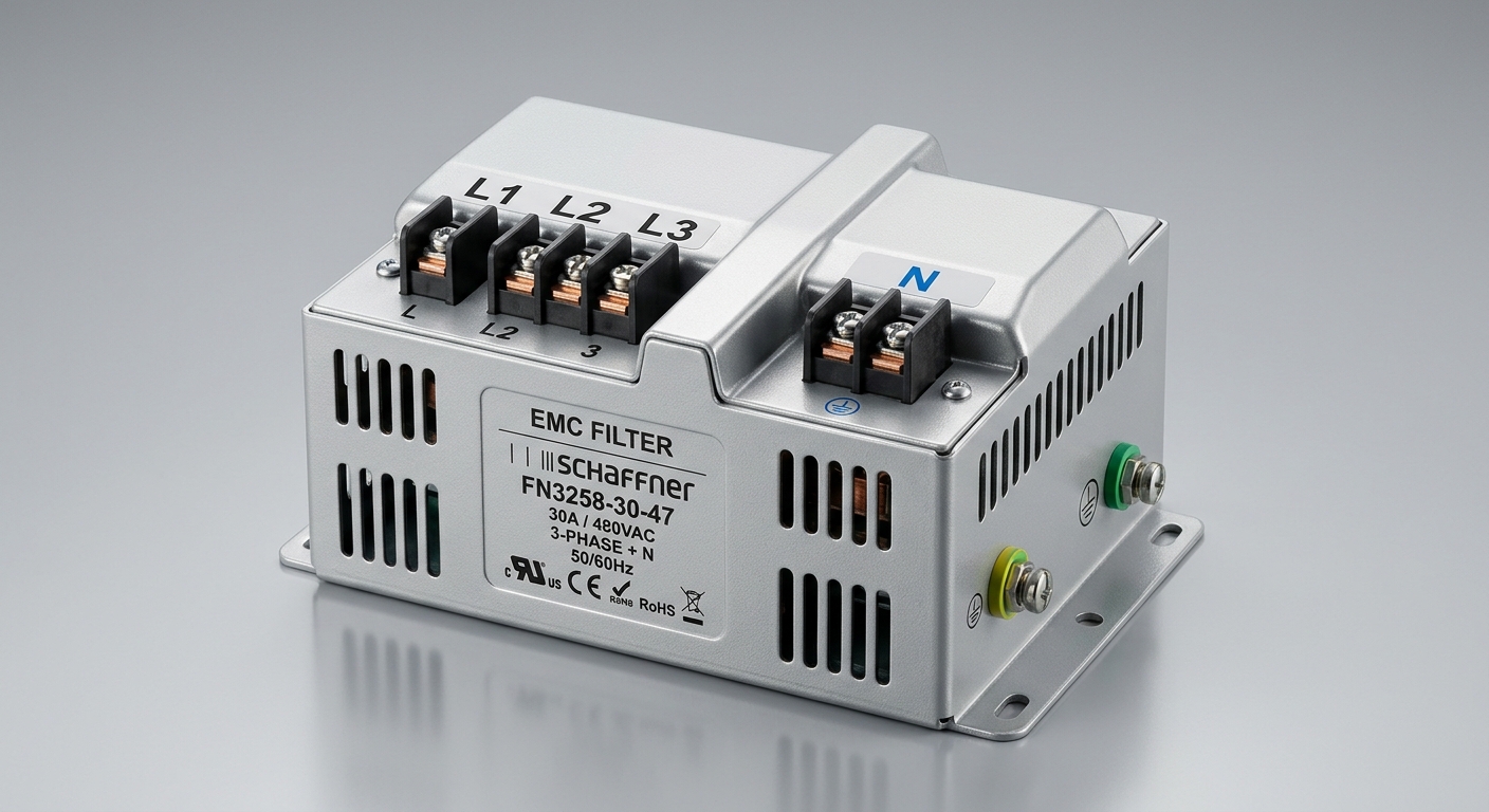
A three phase filter with neutral is a passive EMC network engineered for four-wire (3P+N) power systems operating in industrial and commercial environments. Its defining structural characteristic is the inclusion of a dedicated neutral conductor path within the filter assembly — a feature absent in conventional three phase EMC filters, which process only three line conductors.
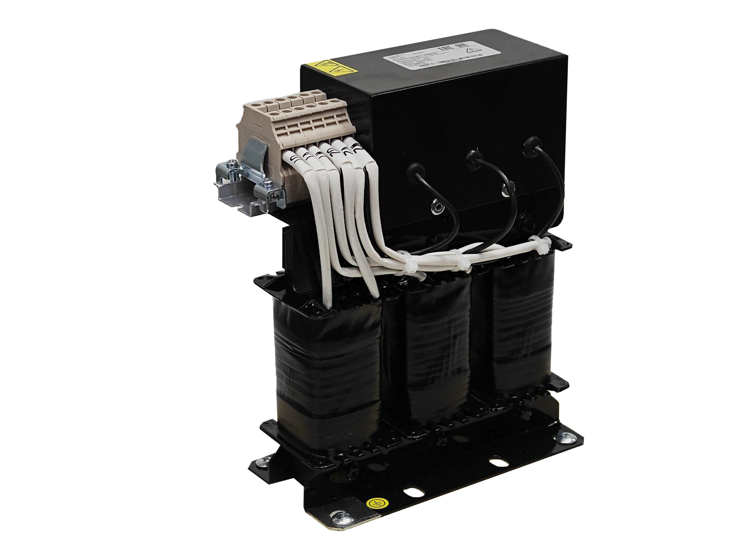
The internal topology consists of four discrete filter branches: one for each of the three phase lines (L1, L2, L3) and one for the neutral (N). Each branch incorporates a series inductor (common-mode choke) and a combination of X-capacitors (connected line-to-line) and Y-capacitors (connected line-to-ground). The neutral branch typically carries its own inductive element, sized according to the expected neutral current under unbalanced load conditions.
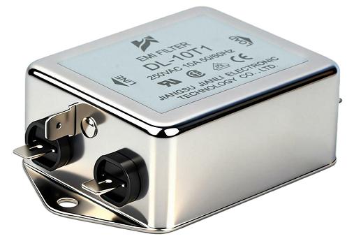
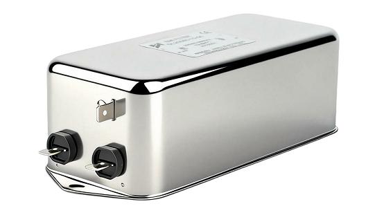
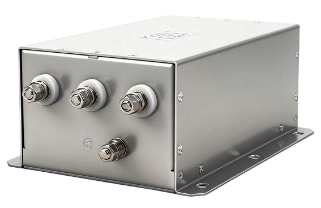
From a form-factor perspective, three phase filters with neutral are available in chassis-mount and DIN-rail configurations. Terminal arrangements follow a standardized input/output layout, with clearly labeled line and neutral terminals on both the line side and the load side. Ground terminals are integral to the housing and must be bonded to the equipment chassis or cabinet ground bus to ensure effective common-mode noise drainage.
The presence of the neutral branch is not merely additive — it fundamentally changes the filter’s ability to suppress zero-sequence currents, which circulate through the neutral in unbalanced three phase systems and are a primary carrier of high-frequency interference.
1.2 How It Works: EMI Suppression Mechanism
Three phase filters with neutral suppress two distinct categories of electromagnetic interference: common-mode (CM) noise and differential-mode (DM) noise.
Common-mode noise appears simultaneously on all conductors relative to ground. It is generated by switching transients in power electronics and travels along all four conductors — including the neutral. The common-mode chokes in each conductor branch present high impedance to CM currents, forcing them to dissipate rather than propagate. Y-capacitors provide a low-impedance return path to ground, effectively shunting residual CM energy away from sensitive equipment.
Differential-mode noise exists between any two conductors and is attenuated by X-capacitors connected across line pairs, combined with the series inductance of each branch. The resulting LC network creates a low-pass characteristic that passes the fundamental power frequency (50 Hz or 60 Hz) while attenuating high-frequency interference above the filter’s corner frequency.
The neutral conductor plays a specific role in zero-sequence noise suppression. In unbalanced loads — common in commercial buildings with single-phase sub-circuits fed from a three phase supply — third-harmonic currents sum rather than cancel in the neutral. A filter without a neutral branch cannot intercept this interference. The neutral inductor in a four-wire filter directly addresses this by presenting impedance to these zero-sequence components before they reach upstream equipment or the supply network.
2. Key Specifications and Selection Parameters
2.1 Critical Electrical Parameters
Selecting the correct three phase filter with neutral requires systematic evaluation of six primary parameters. Mismatching any of these to the actual system conditions will either compromise EMC performance or create safety and reliability risks.
| Parameter | Typical Range | Selection Guidance |
|---|---|---|
| Rated Current (A) | 6 A – 800 A | Must exceed maximum continuous load current; apply derating for elevated ambient temperatures |
| Rated Voltage (V) | 250 V / 480 V / 520 V AC | Match to system nominal voltage with margin for transient overvoltage |
| Neutral Current Rating (A) | 50%–100% of phase rating | Size for worst-case unbalance; 100% neutral rating required for heavily unbalanced loads |
| Leakage Current (mA) | 0.5 mA – 30 mA | Critical for medical, IT, and TN-S systems; low-leakage variants available |
| Insertion Loss (dB) | 30 dB – 80 dB @ 1 MHz | Higher dB values indicate greater attenuation; verify against the noise profile of the connected equipment |
| Mounting Style | Chassis, DIN-rail, panel-mount | Determined by cabinet space, installation density, and thermal management requirements |
Rated current is the most operationally critical parameter. Procurement teams should request the filter’s current derating curve from the manufacturer and apply a minimum 20% safety margin above the calculated maximum load current. Operating a filter at or near its thermal limit accelerates capacitor degradation and increases leakage current drift over time.
Leakage current deserves particular attention in systems where personnel safety or sensitive ground fault protection devices are present. High Y-capacitance values improve CM attenuation but increase leakage current — a direct engineering trade-off that must be resolved based on the specific installation environment.
Neutral current rating is often overlooked in procurement specifications. In systems with significant harmonic distortion (THD > 15%), neutral currents can exceed phase currents. Specifying a filter with a full-rated neutral conductor — equal to the phase conductor rating — is the conservative and recommended approach for VFD-heavy installations.
2.2 Compliance Standards and Certifications
Three phase filters with neutral deployed in professional applications must carry documented compliance with recognized international standards. The following certifications represent the minimum baseline for industrial and commercial procurement:
- IEC/EN 60939-2 / IEC/EN 60939-3: The primary product standards governing passive EMC filters for power lines. Defines test methods for insertion loss, voltage withstand, leakage current, and thermal performance.
- CE Marking (EMC Directive 2014/30/EU + Low Voltage Directive 2014/35/EU): Mandatory for products placed on the European market. Confirms conformity with both electromagnetic compatibility and electrical safety requirements.
- UL Recognition (UL 1283): Required for North American market access. Verifies component-level safety under UL’s Recognized Component program.
- RoHS Compliance (EU Directive 2011/65/EU): Restricts hazardous substances in electrical equipment. Mandatory for EU market access and increasingly required by global OEM supply chain policies.
When evaluating supplier documentation, request test reports from accredited third-party laboratories rather than self-declarations alone. For critical infrastructure applications — data centers, medical facilities, transportation systems — additional national certifications (e.g., CCC for China, KC for Korea) may be required.
3. Application Scenarios in Power Systems
3.1 Typical Industrial and Commercial Use Cases
Three phase filters with neutral are deployed wherever four-wire power systems feed equipment that either generates significant EMI or is sensitive to conducted interference from the supply network.
Variable Frequency Drives (VFDs): VFDs are among the most prolific sources of conducted EMI in industrial environments. Their high-frequency switching generates both CM and DM noise across all conductors, including the neutral. Installing a three phase filter with neutral at the VFD input reduces upstream interference and helps systems meet EN 61800-3 conducted emission limits.
CNC Machinery and Servo Systems: Precision motion control equipment requires a clean power supply to maintain positioning accuracy and prevent servo drive faults. Neutral-line noise from adjacent equipment on the same distribution panel can introduce ground-referenced interference that corrupts encoder signals and triggers nuisance trips.
HVAC Systems with Electronic Controls: Modern HVAC units use variable-speed compressor drives and electronic control boards that are both noise sources and noise victims. In commercial buildings where HVAC shares a distribution panel with IT or lighting loads, neutral-line harmonics are a persistent issue.
Data Center PDUs: Power distribution units in data centers feed large numbers of single-phase server loads from a three phase supply. The resulting load imbalance and harmonic content — primarily third-harmonic currents — create substantial neutral current. A three phase filter with neutral at the PDU input protects upstream UPS and distribution equipment from conducted interference propagating back through the neutral.
3.2 Installation Considerations and System Integration
Correct installation is as important as correct product selection. A properly specified filter installed incorrectly will deliver significantly degraded performance.
Placement: The filter must be installed as close as possible to the equipment it protects — at the power input terminals of the drive, machine, or PDU. Long cable runs between the filter output and the load reintroduce noise pickup and reduce effective attenuation.
Grounding: The filter’s ground terminal must be bonded directly to the equipment cabinet’s ground bus with a short, low-impedance conductor. High-impedance ground connections — caused by long ground leads, corroded connections, or painted mounting surfaces — severely compromise CM attenuation performance.
Cable Routing: Input and output cables must be routed separately to prevent capacitive coupling that bypasses the filter. In high-noise environments, shielded cable on the load side further reduces radiated pickup.
Derating Under High Neutral Current: When neutral currents are expected to approach or exceed phase current levels, verify the filter’s neutral conductor thermal rating and apply appropriate current derating. Operating the neutral winding at excessive current causes localized heating that accelerates insulation degradation and can lead to premature failure.
Conclusion
A three phase filter with neutral delivers targeted EMC protection in four-wire power environments where the neutral conductor carries significant interference — a condition that standard three phase filters are structurally unable to address. The component’s value is realized only when selection, specification, and installation are aligned: the rated current must exceed actual load demand, the neutral rating must account for harmonic imbalance, leakage current must suit the installation environment, and certifications must match the target market.
For procurement teams, the key takeaway is that “three phase EMC filter” and “three phase filter with neutral” are not interchangeable terms. Substituting a three-conductor filter in a four-wire application leaves a direct interference path unaddressed, risking both EMC non-compliance and equipment reliability issues. Aligning engineering specifications with procurement sourcing criteria from the outset eliminates this risk and ensures that the deployed filter delivers its rated performance throughout the system’s operational life.
FAQ
Q1: What is the difference between a standard three phase EMC filter and a three phase filter with neutral?
A standard three phase EMC filter processes only the three line conductors (L1, L2, L3) and is designed for three-wire (delta) systems. A three phase filter with neutral adds a fourth filtered conductor path for the neutral line, making it suitable for four-wire (star/wye) systems. In unbalanced or harmonic-rich loads, the neutral carries significant interference current that a three-conductor filter cannot suppress.
Q2: How do I select the correct rated current for a three phase filter with neutral in a VFD application?
Identify the VFD’s maximum continuous input current from its datasheet. Select a filter with a rated current at least 20% above this value. If the installation environment exceeds 40°C ambient, apply the manufacturer’s temperature derating factor. For VFDs with high input harmonic distortion, also verify the neutral current rating against the calculated third-harmonic neutral current.
Q3: Does a three phase filter with neutral need to be grounded to function correctly?
Yes. Grounding is essential for common-mode noise suppression. The Y-capacitors within the filter drain CM interference to ground — without a low-impedance ground connection, this drain path is broken and CM attenuation is severely degraded. The ground terminal must be bonded directly to the equipment chassis or cabinet ground bus using a short, appropriately rated conductor.