
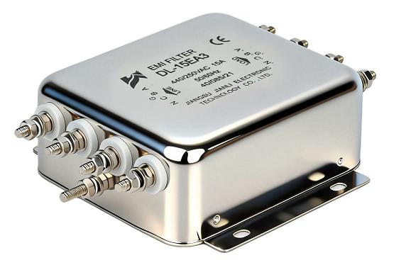
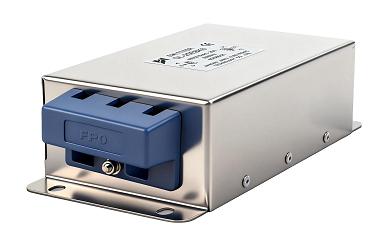
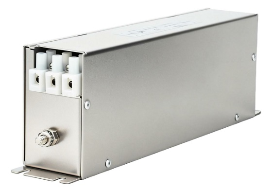
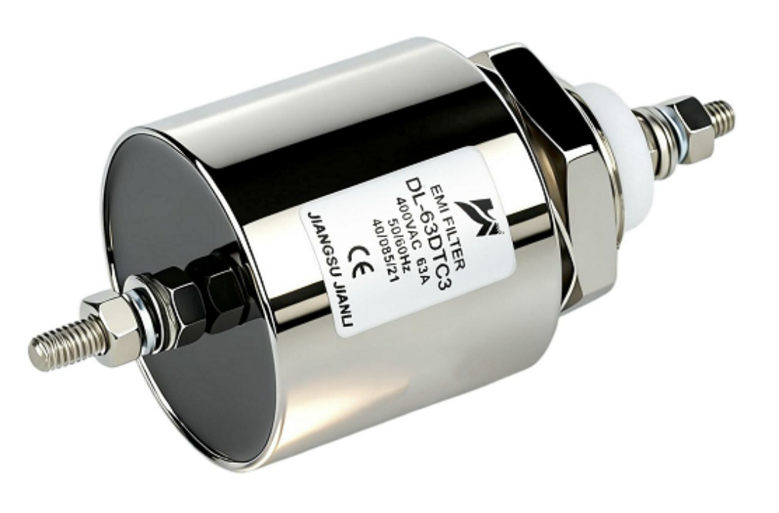
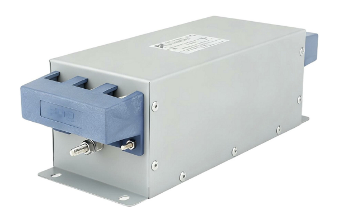
A zero phase filter suppresses EMI/EMC noise while preserving the original phase relationship of the input signal. Engineers should deploy it when phase distortion directly compromises system accuracy, control loop stability, or signal integrity in power electronics.
1. What Is a Zero Phase Filter and Why Does Phase Response Matter?
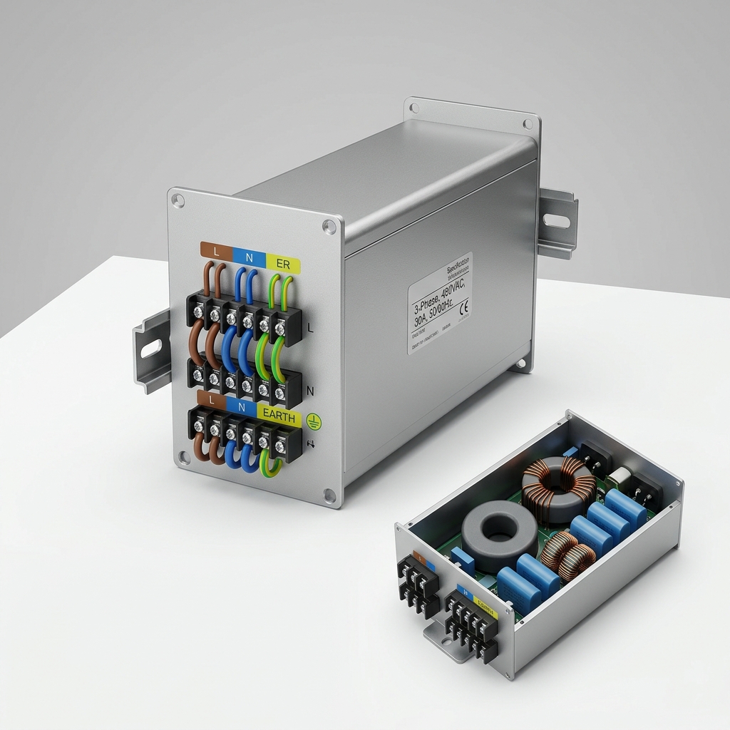
Defining Zero Phase Response in Power Filtering
A zero phase filter is a signal conditioning component designed to attenuate electromagnetic interference without introducing phase shift between input and output signals.
- Phase shift occurs when filter reactive elements (inductors, capacitors) delay frequency components unevenly.
- In conventional LC filters, phase deviation can reach ±45° to ±90° near the cutoff frequency.
- Zero phase designs achieve near 0° phase deviation across the operational bandwidth through symmetric topologies or forward-backward processing techniques.
Why Phase Distortion Is a Critical EMC Parameter
| Parameter | Conventional LC Filter | Zero Phase Filter |
|---|---|---|
| Phase deviation at cutoff | ±45° – ±90° | < ±5° |
| Group delay variation | High (nonlinear) | Minimal (flat) |
| Signal waveform fidelity | Degraded | Preserved |
| Feedback loop impact | Destabilizing risk | Stable |
Phase distortion directly affects:
- Closed-loop control systems where feedback timing governs actuator response.
- Power quality measurement instruments requiring precise voltage/current phase alignment.
- Multi-axis servo drives where phase mismatch across channels causes synchronization errors.
2. Zero Phase Filter Topology vs. Conventional LC Designs
Structural Differences
Conventional LC EMI filters use a single-pass topology: signal enters, reactive elements attenuate noise, signal exits.
- Inductors store energy, causing frequency-dependent phase lag.
- Capacitors introduce leading phase at higher frequencies.
- Net result: nonlinear phase response across the filter’s attenuation band.
Zero phase filter topology addresses this through:
- Balanced differential-mode and common-mode networks that cancel phase asymmetry.
- Forward-reverse processing architecture (in digital implementations) applies the filter twice—once forward, once backward—yielding mathematically zero net phase shift.
- Symmetric ladder networks with precisely matched component values to equalize group delay.
Component-Level Comparison
| Design Element | Standard LC Filter | Zero Phase Filter |
|---|---|---|
| Inductor configuration | Single-ended | Balanced / bifilar wound |
| Capacitor placement | Asymmetric shunt | Symmetric shunt pairs |
| Common-mode choke | Optional | Integrated, high-permeability core |
| Topology complexity | Low | Moderate to high |
| PCB footprint | Compact | 15–30% larger |
Insertion Loss Benchmarks
Zero phase EMI filter performance is evaluated against IEC 61000-4-6 and CISPR 17 standards:
- Differential-mode attenuation: ≥ 40 dB at 150 kHz – 30 MHz.
- Common-mode attenuation: ≥ 50 dB at 10 kHz – 1 MHz.
- Phase deviation benchmark: < ±3° from 50 Hz to 10 kHz for precision applications.
- Insertion loss measurement follows CISPR 17 with 50Ω/50Ω source-load termination.
Filters failing to meet these insertion loss benchmarks under real impedance conditions indicate impedance mismatch—a primary cause of attenuation accuracy degradation.
3. How Impedance Mismatch Affects Zero Phase Filter Attenuation Accuracy
The Mismatch Problem
CISPR 17 specifies insertion loss under ideal 50Ω termination. Real industrial environments present:
- Source impedance: 0.1Ω – 10Ω (low-impedance power supplies).
- Load impedance: Variable, especially with switching loads like VFDs.
- Mismatch ratio: Can reduce rated attenuation by 10–20 dB in worst-case scenarios.
Mitigation Strategies
- Select filters rated under worst-case impedance conditions (0Ω source / ∞Ω load and vice versa).
- Use impedance-adaptive topologies incorporating additional damping resistors.
- Verify attenuation curves published under both 50Ω and real-world impedance test conditions.
- Apply ferrite bead pre-filtering at the filter input to stabilize source impedance.
Impedance mismatch is the single most common cause of field performance diverging from datasheet specifications in zero phase EMC filter deployments.
4. When Do Variable Frequency Drives Require Zero Phase EMI Filtering?
VFD-Generated Noise Profile
Variable frequency drives generate broadband conducted emissions through:
- PWM switching frequencies: Typically 2 kHz – 16 kHz, with harmonics extending to 30 MHz.
- dV/dt transients: Rise times < 1 µs, generating high-frequency common-mode currents.
- Bearing currents: Induced by common-mode voltage, damaging motor bearings over time.
Zero Phase Filter Selection Criteria for VFDs
When a VFD application requires zero phase EMI filtering:
| Condition | Threshold | Filter Action Required |
|---|---|---|
| Cable length (motor to VFD) | > 10 meters | Zero phase common-mode filter |
| Switching frequency | > 8 kHz | Broadband attenuation to 30 MHz |
| Leakage current limit | < 3.5 mA (IEC 60950) | High-impedance Y-capacitor design |
| EMC standard compliance | IEC 61800-3 Cat. C2/C3 | Integrated zero phase filter module |
- VFDs operating in residential or light industrial environments must comply with IEC 61800-3 Category C2, requiring conducted emission limits from 150 kHz to 30 MHz.
- Zero phase filter topology is preferred over standard LC designs when motor encoder feedback signals share the same cable routing, as phase distortion corrupts position data.
- Systems with regenerative braking produce bidirectional noise; zero phase filters handle both current directions without performance asymmetry.
5. Real-World Application Scenarios
Scenario 1: CNC Machining Center with Multi-Axis Servo Control
- Problem: Phase mismatch between servo drive channels caused 0.3° angular positioning error.
- Solution: Zero phase EMC filter installed on each drive input.
- Result: Phase deviation reduced to < 1°; positioning repeatability improved to ±0.005 mm.
Scenario 2: Industrial Solar Inverter Farm (Grid-Tied, 500 kW)
- Problem: Conducted EMI from 48 parallel inverters exceeded EN 55011 Class A limits by 12 dB.
- Solution: Zero phase filter bank with 60 dB common-mode attenuation at 150 kHz.
- Result: Compliance achieved; grid synchronization phase error reduced from 2.1° to 0.2°.
Scenario 3: Medical Imaging Power Supply (MRI Gradient Amplifier)
- Problem: Gradient amplifier switching noise at 20 kHz introduced phase artifacts in image reconstruction.
- Solution: Zero phase filter with < ±2° phase deviation from 1 Hz to 50 kHz.
- Result: Image artifact elimination; compliance with IEC 60601-1-2 (4th edition) EMC requirements.
6. EMI Filter Selection Guide: Choosing the Right Zero Phase Filter
Decision Framework
When evaluating a zero phase EMC filter for industrial equipment:
- Define phase tolerance: Precision servo → < ±3°; general industrial → < ±10°.
- Identify noise type: Common-mode, differential-mode, or mixed.
- Confirm current rating: Derate by 20% for ambient temperatures > 40°C.
- Validate under real impedance: Request CISPR 17 data at 0.1Ω and 100Ω source impedance.
- Check leakage current: Medical/IT equipment typically requires < 0.5 mA.
- Verify mechanical form factor: DIN rail, chassis-mount, or panel-mount configurations.
Key Standards Reference
- CISPR 17: Insertion loss measurement methodology.
- IEC 61000-4-6: Conducted disturbance immunity.
- IEC 61800-3: EMC requirements for variable speed drive systems.
- EN 55011 / EN 55032: Conducted and radiated emission limits.
- IEC 60601-1-2: EMC for medical electrical equipment.
FAQ: Zero Phase Filter in EMI/EMC Systems
Q1: How does zero phase response reduce signal distortion in EMI filters?
By preserving equal phase delay across all frequency components, preventing waveform shape alteration.
Q2: What insertion loss benchmarks define zero phase EMI filter performance?
≥ 40 dB differential-mode and ≥ 50 dB common-mode attenuation per CISPR 17.
Q3: How does zero phase filter topology differ from conventional LC designs?
Uses symmetric balanced networks and matched components to eliminate group delay variation.
Q4: When do variable frequency drives require zero phase EMI filtering?
When cable length exceeds 10 m, switching frequency exceeds 8 kHz, or IEC 61800-3 compliance is required.
Q5: How does impedance mismatch affect zero phase filter attenuation accuracy?
Mismatch between source/load and filter impedance reduces rated attenuation by up to 20 dB.
Q6: What is the phase deviation limit for precision servo applications?
< ±3° deviation from 50 Hz to 10 kHz is the accepted engineering benchmark.
Q7: Can zero phase filters handle bidirectional power flow in regenerative drives?
Yes; symmetric topology ensures consistent attenuation regardless of current direction.
Q8: What leakage current limits apply when selecting a zero phase EMC filter for medical equipment?
IEC 60601-1-2 requires leakage current < 0.5 mA for patient-connected equipment.
Conclusion
Zero phase filters are the correct engineering choice when phase integrity is as critical as noise attenuation. Standard LC filters introduce phase distortion that destabilizes feedback loops, corrupts encoder signals, and compromises power quality measurements. Zero phase filter topology—through balanced networks, symmetric ladder designs, and impedance-matched components—delivers insertion loss performance meeting CISPR 17 benchmarks while maintaining < ±5° phase deviation across operational frequencies.
Key decision triggers for deploying a zero phase EMC filter:
- Multi-axis servo systems requiring synchronization accuracy < 1°.
- VFD installations with cable runs > 10 meters and IEC 61800-3 compliance obligations.
- Grid-tied inverters where phase error directly affects synchronization stability.
- Medical and precision measurement equipment with strict leakage current constraints.
Engineers should validate filter performance under actual site impedance conditions—not solely under CISPR 17’s 50Ω reference—and confirm attenuation curves cover the full 150 kHz to 30 MHz conducted emission band. Selecting a zero phase filter rated for worst-case impedance scenarios ensures field performance matches datasheet specifications.
References & Standards:
- CISPR 17:2011 — Methods of Measurement of the Suppression Characteristics of Passive EMC Filtering Devices
- IEC 61000-4-6:2013 — Immunity to Conducted Disturbances
- IEC 61800-3:2017 — Adjustable Speed Electrical Power Drive Systems, EMC Requirements
- EN 55011:2016+A1:2017 — Industrial, Scientific and Medical Equipment Radio Disturbance Characteristics
- IEC 60601-1-2:2014 (Ed. 4) — Medical Electrical Equipment EMC Requirements
- IEEE Std 1100-2005 — Powering and Grounding Electronic Equipment