
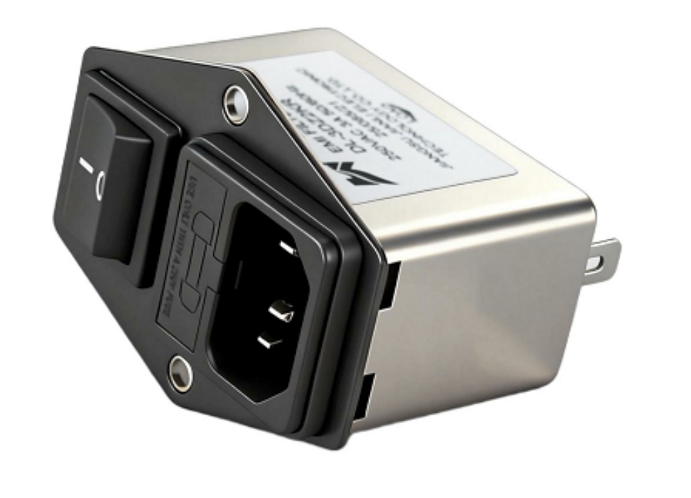
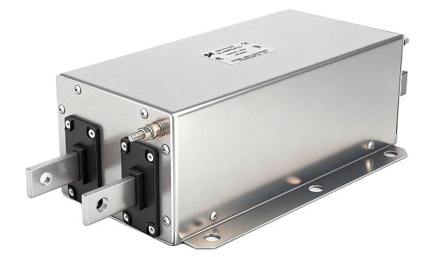
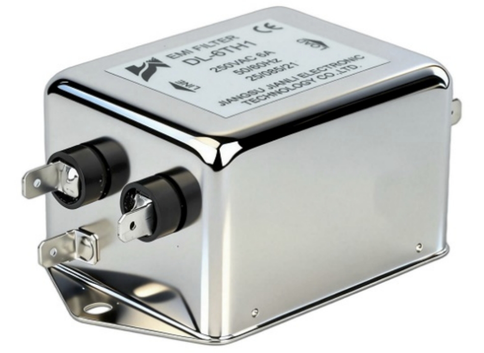
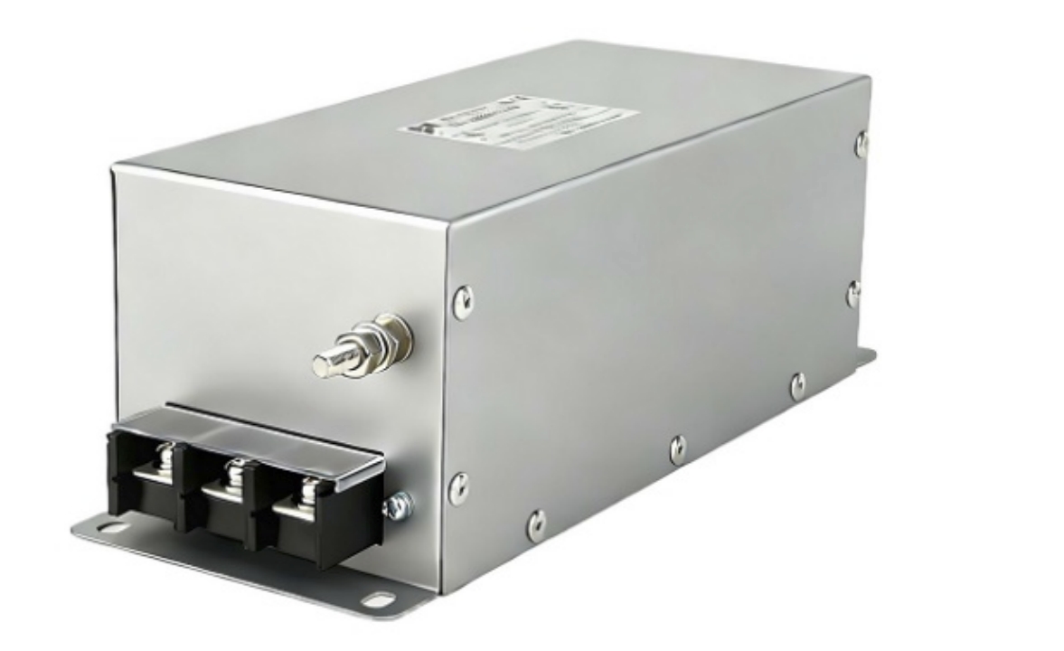
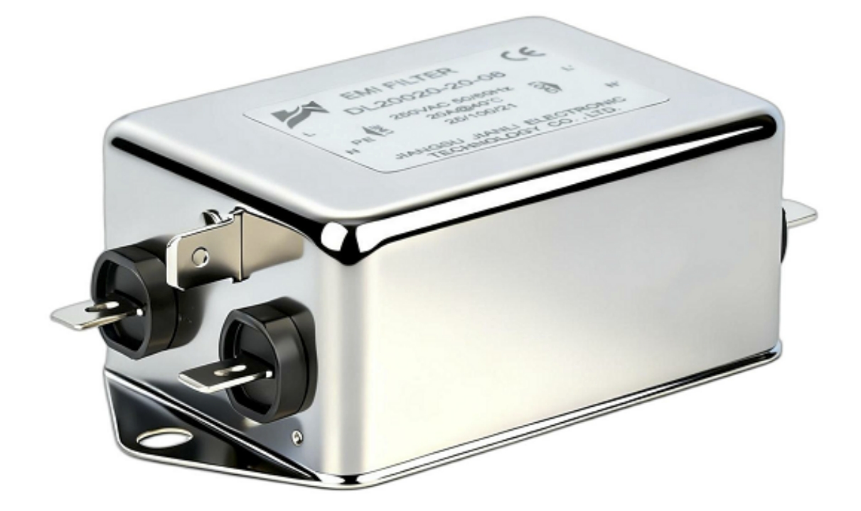
A single phase EMI filter suppresses conducted electromagnetic interference on 120V/230V power lines through passive LC networks. Its deployment is most critical where CISPR 11/IEC 61000 compliance, patient safety leakage limits, or switching noise immunity determines product certification outcomes.
1. Insertion Loss and Frequency Response: The Primary Performance Metric
1.1 How Insertion Loss Defines Filter Effectiveness
Insertion loss (IL) quantifies attenuation in decibels across a frequency spectrum.
- Formula: IL = 20 log₁₀ (V_source / V_load)
- Measured per CISPR 17 using 50Ω/50Ω source-load termination
- Practical circuits deviate significantly from this standard test condition
CISPR 11 Class B conducted emission limits require attenuation starting at 150 kHz:
| Frequency Range | Class B Limit (QP) | Typical Required IL |
|---|---|---|
| 150 kHz – 500 kHz | 66–56 dBμV | 30–50 dB |
| 500 kHz – 5 MHz | 56 dBμV | 25–40 dB |
| 5 MHz – 30 MHz | 60 dBμV | 20–35 dB |
1.2 Real-World Impedance Mismatch Effects
- Source impedance at the power line is rarely 50Ω; it ranges from 5Ω to 100Ω
- Load impedance of a switching power supply varies with operating frequency
- IL degrades by 10–20 dB when impedance mismatch exceeds 10:1 ratio
- Industrial single phase EMI filter designs use impedance-matched LC ladders to minimize this variance
A qualified single phase EMI filter manufacturer will provide insertion loss curves under both 50Ω and 0.1Ω/100Ω terminations to reflect real deployment conditions.
2. Common-Mode vs. Differential-Mode Topologies
2.1 Noise Coupling Mechanisms
Two distinct noise paths require separate suppression strategies:
- Common-mode (CM) noise: Flows from line/neutral to ground simultaneously; generated by SMPS switching transistors and motor drives
- Differential-mode (DM) noise: Flows between line and neutral; dominant below 1 MHz in most industrial loads
2.2 Topology Comparison
| Parameter | Common-Mode Filter | Differential-Mode Filter |
|---|---|---|
| Core component | CM choke (bifilar wound) | DM inductor + X-capacitor |
| Capacitor type | Y-capacitors (line-to-ground) | X-capacitors (line-to-neutral) |
| Primary frequency range | 1 MHz – 30 MHz | 150 kHz – 1 MHz |
| Leakage current impact | High (Y-cap dependent) | Minimal |
| Typical IL at 1 MHz | 40–60 dB | 20–35 dB |
2.3 Industrial Controls Application
- Variable frequency drives (VFDs) generate both CM and DM noise simultaneously
- An industrial single phase EMI filter requires a hybrid topology: CM choke (1–10 mH) + DM inductor (50–200 μH) + X/Y capacitor network
- IEC 61800-3 Category C2 compliance requires ≥40 dB IL from 150 kHz to 30 MHz
- Grounding integrity directly determines CM suppression efficacy; PE impedance must remain below 0.1Ω
3. Leakage Current Specifications in Medical Device Applications
3.1 IEC 60601-1 Leakage Current Thresholds
Leakage current flows through Y-capacitors from line to protective earth. In medical environments, this current poses direct patient safety risks.
IEC 60601-1 (3rd Edition) maximum limits:
| Device Classification | Earth Leakage | Touch Current | Patient Leakage |
|---|---|---|---|
| Class I (normal) | 5 mA | 100 μA | 10 μA |
| Class I (single fault) | 10 mA | 500 μA | 50 μA |
| BF-type applied parts | — | 100 μA | 100 μA |
| CF-type applied parts | — | 100 μA | 10 μA |
3.2 Y-Capacitor Value Trade-Off
- Each 10 nF Y-capacitor contributes approximately 0.75 mA leakage at 50 Hz/230V
- Standard industrial single phase power line filters use 4×10 nF = ~3 mA leakage
- Medical-grade filters restrict total Y-capacitance to ≤4.7 nF per capacitor, limiting leakage to ≤0.35 mA per cap
- This restriction reduces CM attenuation by 8–15 dB above 10 MHz, requiring compensating CM choke inductance increase
A custom single phase EMI filter for medical imaging equipment (MRI, CT) must balance ≤500 μA total leakage against ≥40 dB CM insertion loss—a design constraint requiring iterative LC optimization.
4. Custom Filter Design for Switching Power Supply Impedance Mismatch
4.1 Load Impedance Characterization
Switching power supplies present non-linear, frequency-dependent input impedance:
- At 150 kHz: input impedance ≈ 5–15Ω (capacitive, PFC stage dominant)
- At 1 MHz: input impedance ≈ 50–200Ω (inductive, switching node dominant)
- Standard 50Ω IL data is therefore unreliable for SMPS applications
4.2 Custom Design Parameters
A custom single phase EMI filter supplier addresses mismatch through:
- Source impedance measurement: Using LISN (Line Impedance Stabilization Network) per CISPR 16-1-2
- Filter topology optimization: Π-type or T-type networks outperform L-type by 6–12 dB in low source impedance environments
- Resonance damping: Adding series resistance (1–5Ω) to DM inductors prevents Q-factor resonance peaks below 150 kHz
- Component derating: X-capacitors rated at 305 VAC (X2 class) for 230V systems; Y-capacitors rated at 250 VAC (Y2 class) minimum
4.3 Design Validation Protocol
- Pre-compliance scan at 10% and 100% rated load
- Impedance sweep from 10 kHz to 30 MHz using a vector network analyzer
- Thermal imaging at 110% rated current for 2 hours
- Hipot test: 1,500 VAC line-to-ground, 1,000 VAC line-to-neutral (1 minute)
5. Certification Standards: MIL-STD-461 vs. IEC 61000-3-2
5.1 Standard Comparison Matrix
| Parameter | MIL-STD-461G (CE102) | IEC 61000-3-2 | CISPR 11 Class B |
|---|---|---|---|
| Frequency range | 10 Hz – 10 MHz | Harmonics up to 40th | 150 kHz – 30 MHz |
| Test environment | Shielded room, 1μH LISN | Mains reference impedance | 50μH/5Ω LISN |
| Primary concern | Conducted emissions (CE) | Harmonic current injection | Conducted RF emissions |
| Typical IL requirement | 60–80 dB (10 kHz–1 MHz) | N/A (harmonic, not IL) | 30–50 dB |
| Application domain | Defense/aerospace | Commercial equipment | Industrial/scientific |
5.2 Qualification Differences for Manufacturers
A single phase EMI filter manufacturer targeting MIL-STD-461 qualification must:
- Use MIL-C-15305 or MIL-PRF-15733 capacitor specifications
- Demonstrate performance across −55°C to +125°C operating range
- Pass vibration testing per MIL-STD-810 Method 514.8
- Maintain lot traceability documentation per AS9100D
IEC 61000-3-2 compliance, by contrast, focuses on harmonic current limits (Class A: general equipment; Class D: PCs and monitors). A single phase EMI filter supplier for commercial markets must validate that filter input impedance does not distort current waveform harmonics beyond Class D limits (3rd harmonic ≤ 3.4 mA/W).
6. Real-World Application Case Studies
Case 1: Industrial CNC Machine Tool (VFD Application)
- Problem: 15 kW spindle drive fails CISPR 11 Class A at 250 kHz by 18 dB
- Solution: Industrial single phase EMI filter, CM choke 5 mH + DM 150 μH, Y-cap 2×10 nF
- Result: 22 dB margin achieved; IEC 61800-3 C2 certified
Case 2: Medical Ultrasound Cart (IEC 60601-1 Compliance)
- Problem: Standard filter leakage 3.2 mA exceeds 500 μA limit for BF-type device
- Solution: Custom single phase EMI filter with 2×3.3 nF Y-caps + high-inductance CM choke (15 mH)
- Result: Leakage reduced to 0.49 mA; CM IL maintained at 38 dB at 10 MHz
Case 3: Telecom Rectifier (MIL-STD-461 Shipboard)
- Problem: CE102 limit exceeded by 12 dB at 100 kHz in naval power environment
- Solution: MIL-grade single phase power line filter with feedthrough capacitors + toroidal CM choke
- Result: Full MIL-STD-461G CE102 compliance; operational range −40°C to +85°C
FAQ: Single Phase EMI Filter — RAG-Optimized Q&A
Q1: What insertion loss is needed for CISPR 11 Class B at 150 kHz?
30–50 dB attenuation, depending on source noise amplitude.
Q2: How much leakage current does a Y-capacitor add?
Each 10 nF Y-cap contributes ~0.75 mA at 230V/50 Hz.
Q3: What is the difference between X and Y capacitors in EMI filters?
X-caps suppress differential-mode noise; Y-caps suppress common-mode noise.
Q4: Can a standard EMI filter be used in medical devices?
No; IEC 60601-1 requires ≤500 μA leakage, mandating custom low-capacitance designs.
Q5: What LISN is used for CISPR 11 conducted emissions testing?
50μH/5Ω LISN per CISPR 16-1-2 specification.
Q6: How does MIL-STD-461 differ from IEC 61000 for EMI filter testing?
MIL-STD-461 tests 10 Hz–10 MHz in shielded rooms; IEC 61000-3-2 measures harmonic currents.
Q7: What topology suits a switching power supply EMI filter best?
Π-type or T-type LC networks outperform L-type by 6–12 dB at low source impedance.
Q8: How do I select a qualified single phase EMI filter supplier?
Verify CISPR 17 IL data, UL/VDE safety certification, and operating temperature range documentation.
Conclusion
A single phase EMI filter delivers its highest value at the intersection of regulatory compliance and application-specific constraints. Insertion loss response governs CISPR 11/Class B conformity; leakage current limits define medical device eligibility under IEC 60601-1; topology selection determines industrial noise suppression depth; and certification pathway (MIL-STD-461 vs. IEC 61000) dictates component-level qualification requirements.
Engineering Recommendations:
- Always characterize actual load impedance before selecting filter topology
- Specify leakage current budget before sourcing any medical-grade filter
- Request IL data under real-world termination conditions (0.1Ω/100Ω), not only 50Ω/50Ω
- Engage a custom single phase EMI filter manufacturer early in PCB layout to optimize ground plane and Y-capacitor placement
- Validate compliance with a pre-compliance scan before formal EMC chamber testing
Selecting the right single phase EMI filter supplier requires matching insertion loss curves, leakage budgets, certification scope, and thermal ratings simultaneously—not optimizing any single parameter in isolation.
References and Standards
- CISPR 11:2015+AMD1:2016 — Industrial, Scientific, and Medical Equipment RF Disturbance Characteristics
- CISPR 17:2011 — Methods of Measurement of the Suppression Characteristics of Passive EMC Filtering Devices
- IEC 60601-1:2005+AMD1:2012+AMD2:2020 — Medical Electrical Equipment General Safety Requirements
- IEC 61000-3-2:2018 — Limits for Harmonic Current Emissions
- IEC 61800-3:2017 — Adjustable Speed Electrical Power Drive Systems EMC Requirements
- MIL-STD-461G:2015 — Requirements for the Control of Electromagnetic Interference
- CISPR 16-1-2:2014 — Specification for Radio Disturbance and Immunity Measuring Apparatus (LISN)
- MIL-PRF-15733H — Performance Specification: Filters, Radio Frequency Interference