
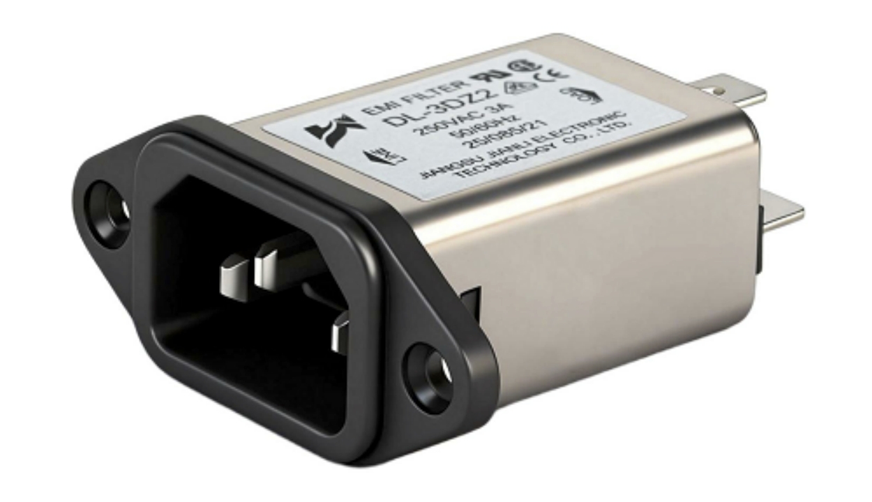
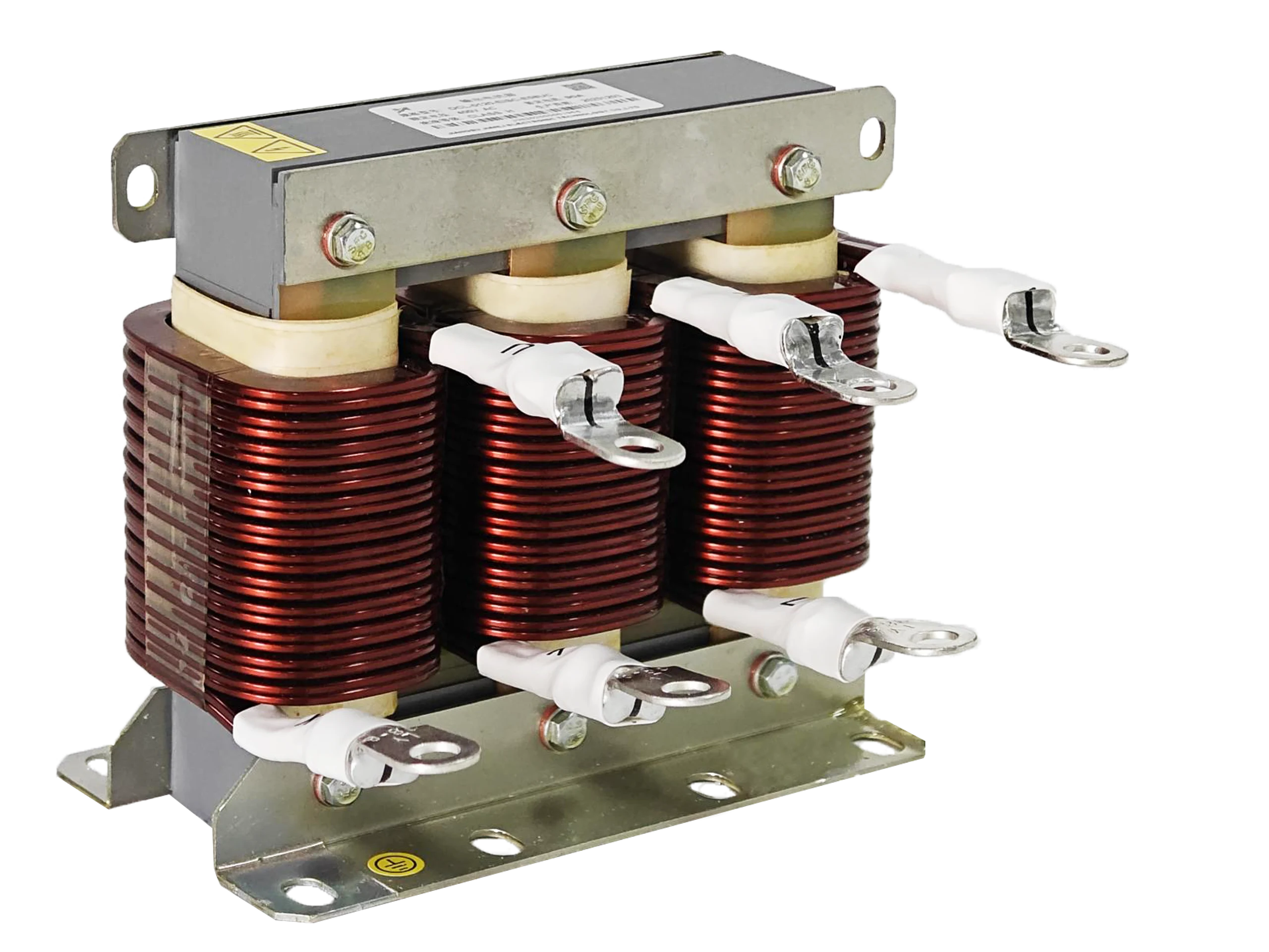
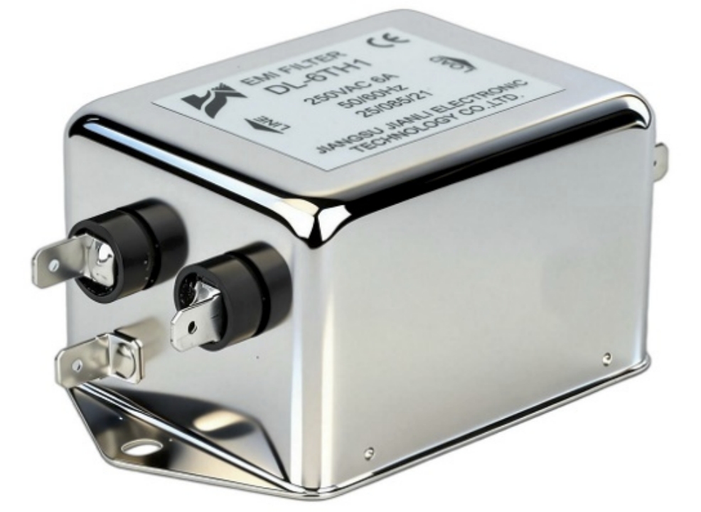
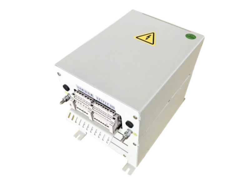
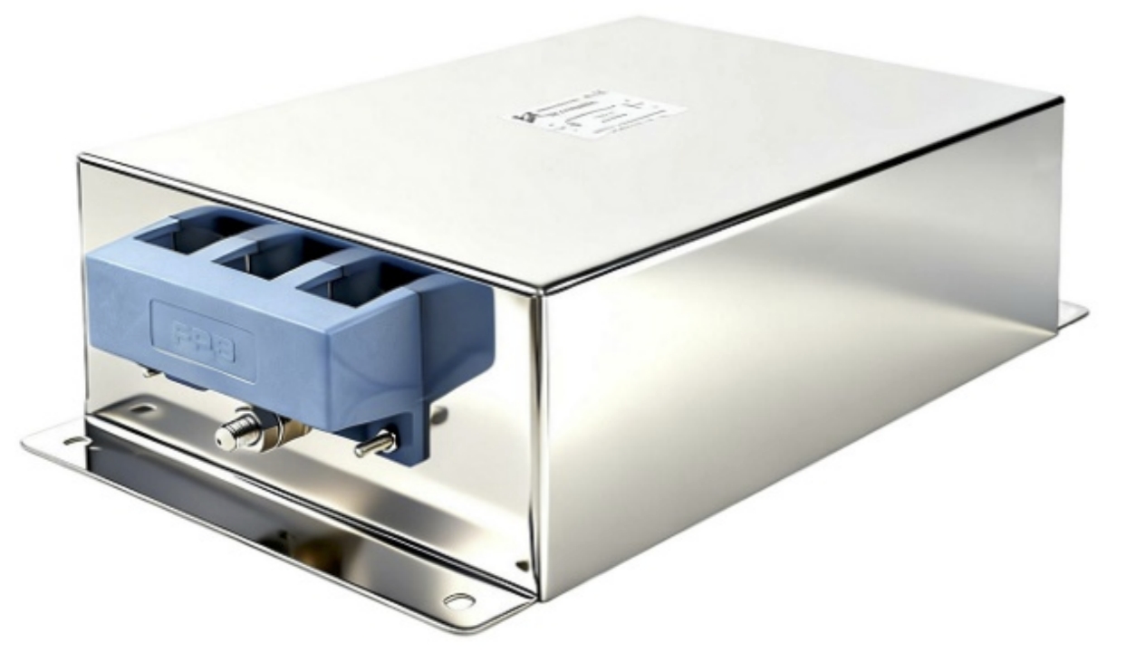
In transformerless PV inverters, AC-side filtering alone cannot suppress DC-side conducted EMI or effectively reduce leakage current. A dedicated DC Filter for PV, combined with an AC output filter, helps address interference on both sides of the inverter, supporting EMC performance, applicable emission requirements, and reliable grid-connected operation.
1. The Fundamental Problem: Why AC Filtering Alone Is Insufficient
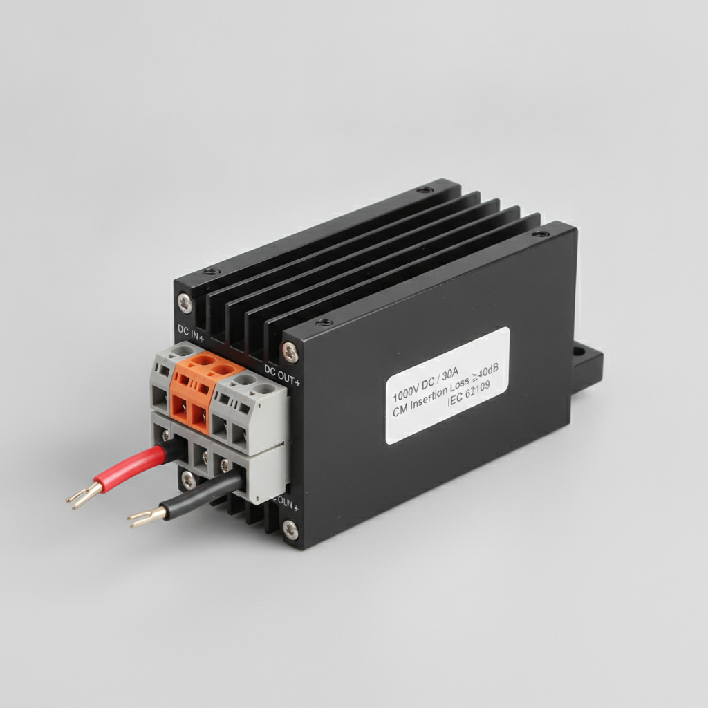
Here is your high-resolution, photorealistic B2B industrial image of the DC EMC filter component:
1.1 Two Distinct Noise Sources, Two Distinct Paths
- DC-side EMI originates at the PV array and propagates through cable capacitance to ground.
- AC-side EMI originates at the inverter output stage, coupled to the grid.
- These are electrically independent noise paths—one filter cannot suppress both.
1.2 The Transformerless Topology Gap
| Parameter | Transformer-Based Inverter | Transformerless Inverter |
|---|---|---|
| DC/AC galvanic isolation | Yes | No |
| Leakage current path | Blocked | Direct to ground |
| DC-side EMI risk | Low | High |
| Requirement for DC filter | Optional | Mandatory |
- In transformerless designs, the PV panel frame connects capacitively to ground.
- Switching events create common-mode voltage transients that drive leakage current through this path.
- An AC filter placed at the output has zero attenuation effect on this upstream noise source.
1.3 Regulatory Pressure Is Increasing
- IEC 61000-6-3 (residential/light industrial emission limits) applies to complete PV systems, not just inverter output.
- EN 61000-3-2 governs harmonic current on the AC side—a separate requirement entirely.
- Failing DC-side conducted emission tests is now a primary cause of CE mark rejection for residential inverters below 6 kW.
2. DC-Side vs. AC-Side Conducted EMI: A Technical Comparison
2.1 Frequency Spectrum Differences
- DC-side noise: Dominated by common-mode (CM) interference in the 150 kHz–30 MHz band, driven by MPPT switching and boost converter operation.
- AC-side noise: Primarily differential-mode (DM) harmonics at switching frequency fundamentals (16–100 kHz) and their sidebands.
- These spectra partially overlap but require different filter topologies to address.
2.2 Insertion Loss Requirements for Compliance
| Noise Type | Frequency Band | Required Insertion Loss (IEC 61000-6-3) |
|---|---|---|
| CM, DC side | 150 kHz – 30 MHz | ≥ 40 dB |
| DM, DC side | 150 kHz – 1 MHz | ≥ 20 dB |
| CM, AC side | 150 kHz – 30 MHz | ≥ 35 dB |
| DM, AC side | 10 kHz – 150 kHz | ≥ 25 dB |
- A DC filter for PV must achieve ≥40 dB CM insertion loss across 150 kHz–30 MHz to meet Class B limits.
- AC filters are not designed or tested to these DC-side specifications.
2.3 Leakage Current: The Safety Dimension
- IEC 62109-1 limits leakage current to 300 mA (RMS) for grid-tied PV inverters.
- VDE 0126-1-1 (Germany) enforces a 30 mA threshold with 300 ms disconnection time.
- AC-only filtering does not interrupt the CM current loop between the PV array, stray capacitance, and ground.
- Only a properly designed photovoltaic DC filter with Y-capacitors and CM choke placed at the DC input can reduce this loop impedance.
3. How MPPT Switching Frequency Affects DC Filter Design
3.1 Stress on DC Filter Capacitors
- MPPT algorithms typically operate at 1–100 Hz perturbation rates, but the boost converter switching frequency ranges from 16 kHz to 100 kHz in modern designs.
- Higher switching frequency → higher ripple current through DC-link capacitors → accelerated dielectric aging.
- Capacitor lifetime follows the Arrhenius equation: every 10°C rise in core temperature halves operational life.
3.2 Capacitor Selection Criteria
| Capacitor Type | Ripple Current Rating | Temperature Stability | Recommended Use |
|---|---|---|---|
| Film (PP) capacitor | High | Excellent (–55°C to +105°C) | Y-capacitor in DC filter |
| Class X2 capacitor | Medium | Good | DM suppression, DC side |
| Electrolytic (Al) | High | Poor above 85°C | DC link bulk only |
| MLCC (X7R) | Low | Good | High-frequency bypass |
- For systems with MPPT switching at 50 kHz+, polypropylene film capacitors rated ≥ 310 V AC are the industry standard for DC filter Y-capacitor positions.
- Capacitor degradation rates increase nonlinearly when ripple current exceeds 80% of rated value.
3.3 CM Choke Core Material Selection
- Nanocrystalline cores provide high permeability (μ > 20,000) across 10 kHz–1 MHz—optimal for DC-side CM choke.
- Ferrite (MnZn) cores are effective above 1 MHz but saturate at lower DC bias.
- For PV systems with string voltages up to 1,500 V DC, choke cores must be rated for DC bias without saturation.
4. Why Dual-Side EMC Filtering Is Now the Industry Standard
4.1 The Compliance Case
- IEC 61000-6-3 + IEC 62109-1 + EN 50178 together create overlapping requirements that no single filter position can satisfy.
- Dual-side filtering (DC input + AC output) is explicitly recommended in IEC TR 61000-5-6 for power conversion systems.
- Grid operators in Germany, Italy, and Australia now require third-party EMC test reports covering both DC and AC ports.
4.2 Efficiency and Cost Trade-offs
- A well-designed DC filter for PV adds 0.3–0.8% insertion loss to system efficiency at full load.
- Dual-side filter BOM cost typically represents 2–4% of total inverter cost for residential units (3–10 kW).
- Failure to comply results in: re-testing fees (€5,000–€15,000 per test cycle), market access delays (4–12 weeks), and potential field recalls.
Cost-benefit summary:
- Filter cost: ~€15–€40 per residential inverter unit
- Non-compliance cost: €5,000+ per test cycle + recall risk
- ROI of dual-side filtering: clearly positive at any production volume above 500 units/year
4.3 Real-World Application Scenarios
Scenario A – Residential Rooftop (3–6 kW, Germany)
- Topology: Transformerless H5 or HERIC
- Requirement: VDE 0126-1-1 (30 mA leakage limit)
- Solution: DC filter with CM choke (nanocrystalline) + Y-caps + AC EMC filter
- Result: Leakage current reduced from 180 mA to 12 mA; CE mark achieved on first submission
Scenario B – Commercial Rooftop (50–100 kW, Italy)
- Topology: Three-phase transformerless, 1,000 V DC string
- Requirement: CEI 0-21, IEC 61000-6-3 Class A
- Solution: Dual-side EMC filter solar configuration with DM inductors on DC side
- Result: Conducted emission reduced by 42 dB at 500 kHz; grid connection approval in 6 weeks
Scenario C – Utility-Scale Ground Mount (1 MW+, Australia)
- Topology: Central inverter with 1,500 V DC bus
- Requirement: AS/NZS 4268, grid operator EMC schedule
- Solution: Rack-mounted photovoltaic DC filter bank at combiner box output
- Result: Common-mode noise floor reduced to –10 dBμV/m; no interference to SCADA communications
5. Selecting the Right DC Filter for PV: Key Specifications
- Voltage rating: Must exceed maximum open-circuit string voltage (V_OC × 1.25 safety factor)
- Current rating: Continuous DC current + 20% margin for transient overload
- Insertion loss: ≥40 dB CM at 150 kHz–30 MHz (verify with CISPR 17 test data)
- Operating temperature: –40°C to +85°C for outdoor/combiner box mounting
- Enclosure rating: IP54 minimum for indoor inverter room; IP65 for combiner box installation
- Certifications: UL 1741, IEC 62109-2, CE marking with EMC test report
FAQ
Q1: How does DC-side conducted EMI differ from AC-side in transformerless PV inverters?
DC-side EMI is common-mode, driven by stray capacitance to ground; AC-side is primarily differential-mode harmonic current.
Q2: What insertion loss does a DC filter require for IEC 61000-6-3 PV compliance?
Minimum 40 dB common-mode insertion loss across 150 kHz to 30 MHz.
Q3: How does MPPT switching frequency affect DC filter capacitor degradation?
Higher switching frequency increases ripple current; exceeding 80% of the ripple rating accelerates capacitor aging nonlinearly.
Q4: Why does AC-only filtering fail leakage current limits in grid-tied PV?
AC filters do not interrupt the CM loop between PV array stray capacitance and ground—the leakage path remains open.
Q5: How do dual-side EMC filters impact PV inverter efficiency?
Dual-side filters reduce efficiency by 0.3–0.8% but eliminate compliance failure costs exceeding €5,000 per test cycle.
Q6: What capacitor type is best for a photovoltaic DC filter?
Polypropylene film capacitors rated ≥310 V AC, with high ripple current rating and wide temperature range.
Q7: Is a DC filter required for string inverters with transformers?
Generally optional; transformer isolation blocks the DC-side CM current path to ground.
Q8: Can one combined filter replace separate DC and AC filters?
No—DC and AC ports have different noise spectra, impedance requirements, and safety isolation needs.
Conclusion
AC filtering addresses grid-side harmonic compliance. It does not—and cannot—suppress DC-side conducted EMI or control leakage current in transformerless PV systems. The technical evidence is unambiguous: a dedicated DC filter for PV is not optional for modern grid-tied installations.
Key findings:
- DC-side CM noise requires ≥40 dB insertion loss; AC filters provide zero attenuation at the DC port
- Leakage current limits (30–300 mA) cannot be met without DC-side CM choke and Y-capacitor networks
- Dual-side EMC filter solar configurations add 2–4% to inverter BOM cost while eliminating re-test and recall risk
- MPPT switching frequency directly determines DC filter capacitor specification and lifetime
Professional recommendation: Specify a photovoltaic DC filter at the design stage, not as a retrofit. Verify CM insertion loss with CISPR 17 test data from the component supplier. For systems above 1,000 V DC, require nanocrystalline CM choke cores and film capacitors with documented ripple current derating curves.
References and Standards
- IEC 61000-6-3:2020 — Electromagnetic compatibility: Emission standard for residential environments
- IEC 62109-1:2010 / IEC 62109-2:2011 — Safety of power converters for PV power systems
- VDE 0126-1-1:2013 — Automatic disconnection device for PV installations
- CISPR 17:2011 — Methods of measurement of the suppression characteristics of passive EMC filtering devices
- IEC TR 61000-5-6:2002 — Mitigation of external EM influences
- EN 50178:1997 — Electronic equipment for use in power installations
- Kerekes, T. et al. (2011). “Evaluation of three-phase transformerless photovoltaic inverter topologies.” IEEE Transactions on Power Electronics, 26(8), 2202–2211.
- Araújo, S.V. et al. (2010). “Highly efficient single-phase transformerless inverters for grid-connected PV systems.” IEEE Transactions on Industrial Electronics, 57(9), 3118–3128.