
Abstract
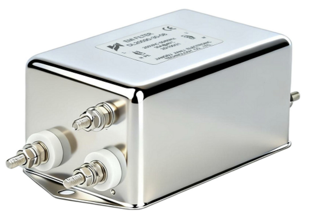
As photovoltaic systems scale in power density and complexity, electromagnetic interference on the DC side of inverters has emerged as a critical engineering challenge—one that directly affects grid-connection approval, equipment longevity, and regulatory compliance. A DC Filter for PV is no longer an optional add-on; in many deployment scenarios, it is a prerequisite for passing EMC certification and ensuring stable operation in electromagnetically sensitive environments.
This article examines the root causes of DC-side conducted EMI in PV inverters, the regulatory frameworks that define compliance thresholds, the technical parameters governing filter selection, and the commercial scenarios where DC-side filtering transitions from a best practice to an absolute necessity. Whether you are designing a utility-scale ground-mount plant, a commercial rooftop system, or a hybrid storage-plus-solar installation, understanding when and why to deploy a DC Filter for PV is fundamental to delivering a compliant, reliable system.
1. EMI on the DC Side of PV Inverters: Root Causes and Risk Factors
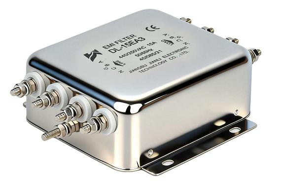
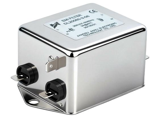
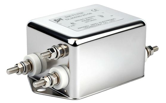
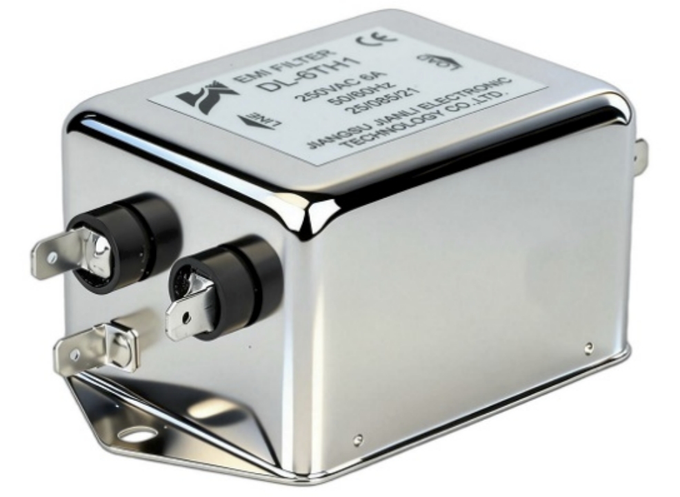
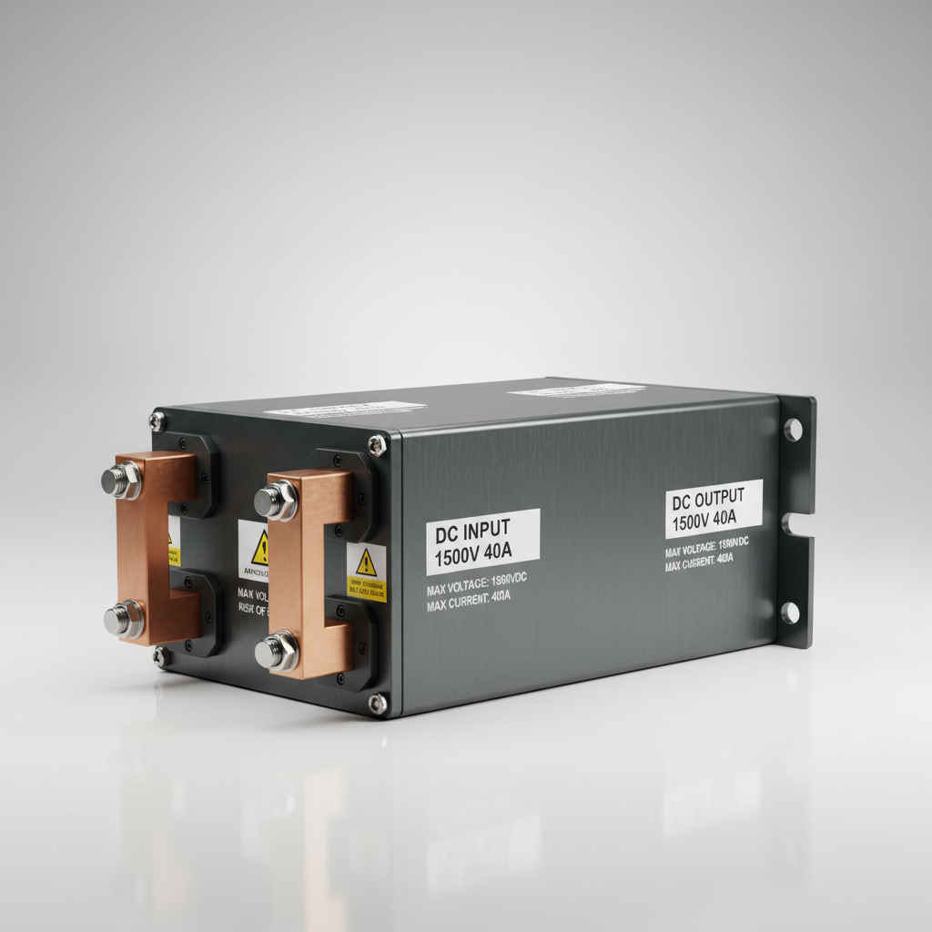
Here is the photorealistic B2B industrial image of the DC EMI filter you requested:
1.1 How PV Inverter Switching Generates DC-Side Conducted EMI
Modern PV inverters rely on high-frequency switching devices—IGBTs and MOSFETs—operating at switching frequencies typically ranging from 8 kHz to 50 kHz. Each switching transition generates steep voltage and current edges (high dV/dt and dI/dt), which propagate as broadband noise across both the AC and DC ports of the inverter.
On the DC side, two distinct noise modes are present:
- Common-mode (CM) noise: Current flows through parasitic capacitances between PV module frames, mounting structures, and ground. This path is particularly problematic in large string arrays where the aggregate parasitic capacitance to earth can reach hundreds of nanofarads.
- Differential-mode (DM) noise: Conducted along the positive and negative DC bus conductors, typically dominant at lower frequencies but still capable of exceeding regulatory limits in high-power systems.
The coupling mechanism is primarily capacitive. Stray capacitance between PV cell laminate and the grounded aluminum frame creates a low-impedance return path for high-frequency CM currents. Without attenuation at the DC input port, these currents re-enter the inverter, radiate from cable runs, and couple into adjacent equipment.
1.2 System Configurations That Amplify EMI Risk
Certain system architectures inherently generate higher EMI levels, making a PV inverter EMI filter on the DC side more critical:
- Long DC cable runs: Cable lengths exceeding 30–50 meters act as efficient antennas, radiating conducted noise and increasing impedance mismatch. Every additional meter of unshielded DC cable increases the effective emission antenna area.
- High power-density inverters: Compact string and central inverters operating above 50 kW in reduced footprints push switching frequencies higher to manage thermal density, directly increasing high-frequency noise amplitude.
- Multi-string parallel configurations: Parallel string connections multiply the aggregate parasitic capacitance to ground, amplifying common-mode current magnitudes proportionally.
- Transformerless topologies: The absence of a galvanic isolation transformer eliminates a natural CM noise barrier. Transformerless inverters—dominant in residential and commercial markets due to their efficiency and cost advantages—require dedicated DC-side filtering to compensate for this missing isolation stage.
These factors compound in large-scale installations, making DC side EMI suppression for PV a design-stage consideration rather than a retrofit afterthought.
2. EMC Compliance Requirements for Photovoltaic Inverters
2.1 Applicable Standards and Regulatory Frameworks
PV inverters are subject to multiple overlapping EMC standards that define conducted emission limits across the DC and AC ports. The primary frameworks include:
- IEC 61000-6-2 / IEC 61000-6-4: Generic immunity and emission standards for industrial environments, establishing baseline conducted and radiated emission limits applicable to inverter installations in industrial and commercial settings.
- EN 55011 (CISPR 11): Covers industrial, scientific, and medical equipment. Class A limits apply to industrial installations; Class B limits apply to residential and light commercial use. Frequency coverage spans 150 kHz to 30 MHz for conducted emissions.
- IEC 62920: The dedicated EMC standard for power conversion equipment used in PV systems, specifying both conducted and radiated emission limits and immunity requirements specifically calibrated to PV inverter operating conditions.
| Standard | Region | Frequency Range | Class | DC Filter Mandate | Key Test |
|---|---|---|---|---|---|
| IEC 62920 | Global | 150 kHz – 30 MHz | A / B | Strongly recommended | Conducted emission, DC port |
| EN 55011 | EU / CE mark | 150 kHz – 30 MHz | A / B | Required for Class B | Conducted emission |
| IEC 61000-6-4 | Global | 150 kHz – 30 MHz | A | Situational | Conducted emission |
| FCC Part 15 | USA | 450 kHz – 30 MHz | A / B | Case-dependent | Conducted & radiated |
| GB/T 24337 | China | 150 kHz – 30 MHz | A | Required for grid tie | Conducted emission |
2.2 When DC-Side Filtering Is Mandated or Strongly Recommended
Regulatory mandates for EMC compliance for photovoltaic inverters become binding in several specific scenarios:
Certification test failures are the most direct trigger. When an inverter fails conducted emission testing at the DC port—typically measured at the point of connection between the PV string and inverter input—a DC filter is the fastest corrective path. AC-side filtering alone cannot address noise originating from the DC bus.
Grid operator interconnection requirements increasingly specify EMC performance levels as a condition of grid-connection approval, particularly in Europe and China. Utility-scale projects above 1 MW routinely face enhanced EMC scrutiny during commissioning audits.
Installation environment determines the applicable class limits. Commercial rooftop systems co-located with sensitive IT infrastructure must meet Class B limits—the more stringent threshold. Ground-mount utility plants typically operate under Class A limits but face stricter scrutiny when located near communication infrastructure or within electromagnetic compatibility zones.
3. DC Filter for PV: Technical Specifications and Selection Criteria
3.1 Core Parameters and Electrical Ratings
Selecting the correct DC Filter for PV requires matching the filter’s electrical ratings to the system’s operating envelope:
- Rated DC voltage (Vdc): Must exceed the maximum open-circuit string voltage, including temperature derating. Systems using 1500 Vdc string configurations require filters rated at minimum 1500 Vdc, with appropriate safety margins.
- Rated DC current (Idc): Must accommodate the maximum short-circuit current of all parallel strings. Undersizing causes thermal stress and premature failure.
- Insertion loss (dB): The primary performance metric, typically specified across 150 kHz–30 MHz. Effective DC filters for PV applications deliver 30–60 dB of CM attenuation in the critical 150 kHz–1 MHz band.
- Leakage current (mA): Critical for transformerless systems where ground leakage is a safety and performance concern. Leakage current must remain within inverter manufacturer specifications and local safety codes—typically below 300 mA for residential systems.
- Operating temperature range: Outdoor and enclosure-mounted filters must function reliably from -40°C to +85°C to match inverter thermal ratings.
3.2 Filter Topology and Component Considerations
The internal architecture of a DC filter determines its performance profile:
- Common-mode chokes: Wound on high-permeability nanocrystalline or ferrite cores, these are the primary CM attenuation elements. Core material selection governs the effective frequency range and saturation behavior under DC bias.
- X-capacitors: Connected across the DC bus for differential-mode noise suppression. Must be rated for DC voltage with appropriate ripple current handling.
- Y-capacitors: Connected from each DC conductor to the protective earth for CM noise diversion. Capacitance values are constrained by leakage current limits.
- Topology selection: π-type filters (capacitor–inductor–capacitor) offer superior high-frequency attenuation and are preferred for high-power applications. L-type configurations are adequate for lower-power strings where insertion loss requirements are moderate.
- Hi-Pot (dielectric withstand) rating: Filters must pass high-voltage insulation testing—typically 2 kVdc or higher—to ensure long-term reliability under PV system fault conditions.
4. Application Scenarios and Commercial Value of DC-Side EMI Suppression
4.1 Typical Use Cases Where DC Filtering Is Necessary
Certain deployment contexts make a DC Filter for PV non-negotiable:
- Utility-scale ground-mount plants: Multi-megawatt installations with centralized or string inverters involve hundreds of parallel strings and kilometers of DC cabling. The cumulative parasitic capacitance and cable radiation make DC filtering essential for passing grid-connection EMC audits.
- Commercial and industrial BESS+PV hybrid systems: When battery energy storage systems share a DC bus with PV arrays, the interaction between inverter switching and battery management system electronics creates complex noise environments requiring staged DC-side filtering.
- EMI-sensitive co-location sites: PV installations on telecom base stations, data centers, or near medical facilities operate within strict electromagnetic compatibility zones. In these environments, exceeding conducted emission limits can interfere with licensed radio equipment or sensitive diagnostic instruments—making Class B compliance with DC filtering a contractual obligation.
4.2 System-Level Benefits Beyond EMC Compliance
The commercial value of DC-side EMI filtering extends well beyond regulatory checkboxes:
- Extended inverter MTBF: Reducing high-frequency noise stress on inverter input capacitors and gate driver circuits directly lowers component failure rates, extending mean time between failures in high-cycling environments.
- Reduced O&M costs: Fewer nuisance trips and component replacements translate to measurable reductions in operations and maintenance expenditure over a 25-year plant lifetime.
- Accelerated grid-connection timelines: Projects that arrive at commissioning with pre-validated EMC performance—including documented DC filter insertion loss data—move through utility interconnection approval faster, reducing financing carrying costs on large capital projects.
- Improved system reliability ratings: Institutional investors and EPC contractors increasingly require documented EMC compliance as part of technical due diligence, making DC filter integration a commercial differentiator in competitive project bids.
FAQ
1. At what inverter power level does a DC filter for PV become necessary?
There is no universal power threshold, but practical experience indicates that string inverters above 25 kW and central inverters above 100 kW operating in transformerless configurations consistently benefit from dedicated DC-side filtering. Below these levels, integrated inverter-side filtering may be sufficient, but this must be verified through conducted emission testing against the applicable standard.
2. Can the AC-side EMI filter replace or eliminate the need for DC-side filtering in a PV system?
No. AC-side filters address noise propagating toward the grid from the inverter’s AC output port. DC-side conducted emissions originate upstream of the inverter’s switching stage and travel through the DC input port. These are electrically separate noise paths. An AC filter provides no attenuation for DC-port emissions measured per IEC 62920 or EN 55011.
3. What certifications should a DC filter for PV carry to satisfy grid-connection and EMC compliance requirements?
At minimum, look for CE marking (indicating conformity with EU EMC Directive 2014/30/EU), IEC 62920 test reports, UL or TÜV component certification for the rated voltage class, and RoHS compliance documentation. For Chinese grid-connection projects, GB/T compliance documentation is additionally required.
Conclusion
A DC Filter for PV becomes necessary at the intersection of three converging factors: high-frequency switching topologies that generate broadband DC-side conducted noise, system configurations—particularly transformerless designs and long cable runs—that amplify EMI propagation, and regulatory frameworks that impose enforceable emission limits on PV inverter DC ports.
The compliance landscape, anchored by IEC 62920, EN 55011, and increasingly stringent grid-operator interconnection requirements, makes DC-side filtering a design-stage necessity for commercial and utility-scale projects rather than a post-certification remedy. Beyond compliance, integrating a purpose-built DC Filter for PV delivers measurable operational value: lower inverter failure rates, reduced maintenance costs, faster grid-connection approval, and a stronger technical due diligence profile for project financing.
For engineers and procurement teams specifying PV systems today, the question is not whether DC filtering will eventually be required—it is whether it is engineered in from the start or added reactively at higher cost and schedule impact.