
Abstract
As electric vehicle architectures grow more complex—spanning 400V and 800V platforms, multi-domain power electronics, and high-frequency switching converters—electromagnetic interference (EMI) has become one of the most critical engineering challenges in EV development. The EV DC filter sits at the intersection of power quality, system stability, and regulatory compliance, serving as a frontline defense against high-frequency noise and voltage ripple that threaten battery management systems, motor controllers, and onboard chargers.
This article is for early-stage researchers and EV development engineers who need a clear, technically grounded understanding of what a DC filter does, how it is specified, where it is deployed, and why omitting it in the design phase creates compounding downstream risks. From LC network fundamentals to CISPR 25 compliance and 800V platform procurement decisions, this guide covers the complete value chain—giving you the knowledge to integrate DC filtering intelligently from the earliest stages of system architecture.
1: Understanding the DC Filter in Electric Vehicle Systems
1.1: What Is a DC Filter and How Does It Work in an EV?
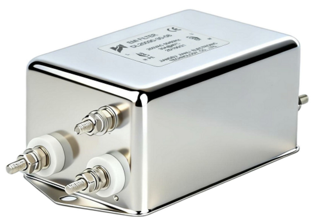
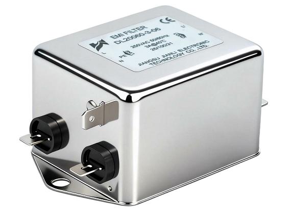
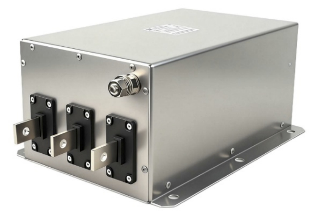
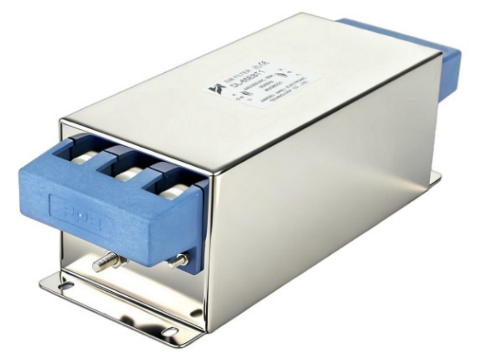
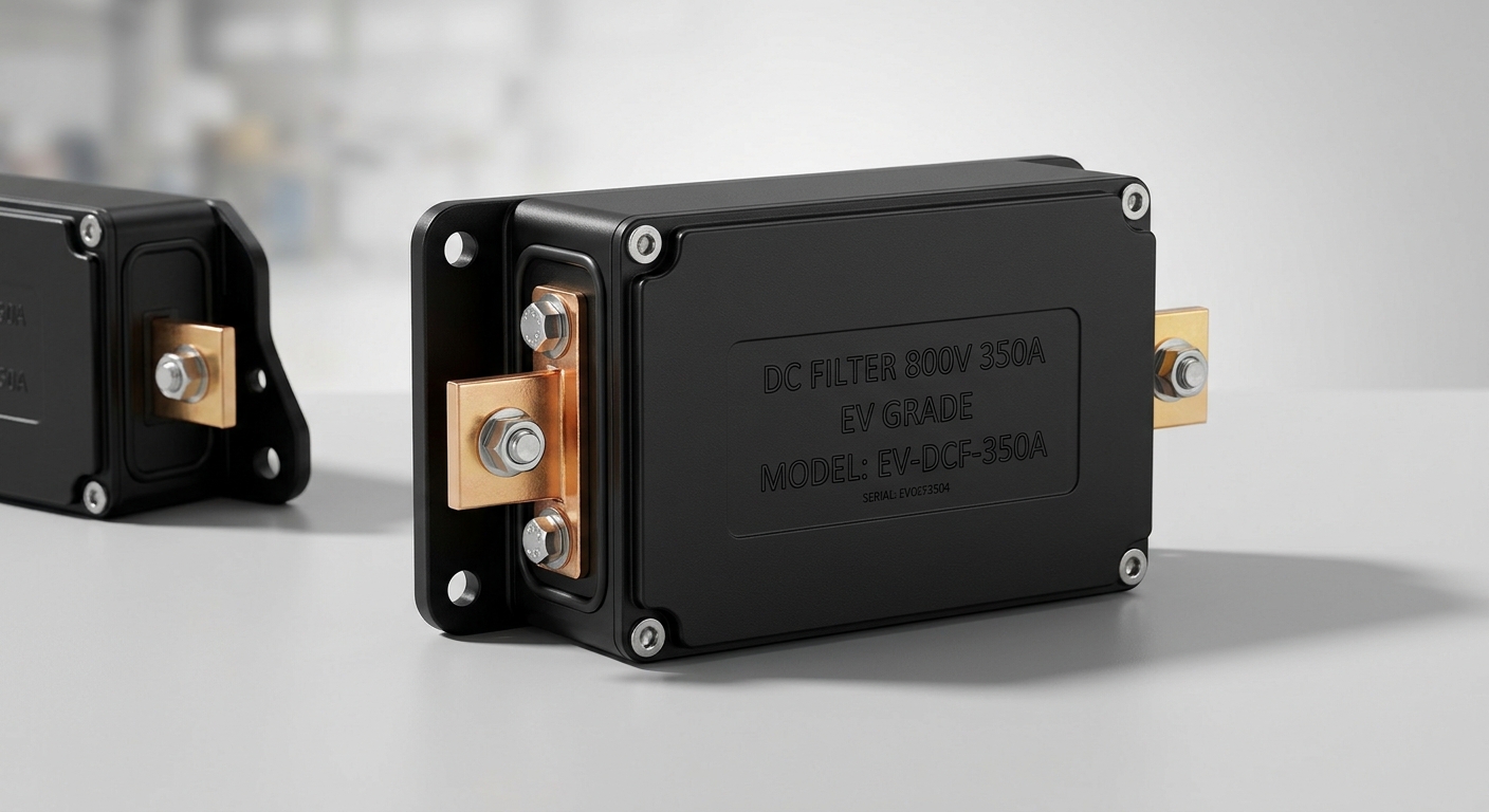
A DC filter for an EV is a passive electromagnetic filtering component installed on the direct current bus of an electric vehicle’s power system. Its primary function is to suppress high-frequency noise and voltage ripple generated by power electronic switching devices—most notably the inverter, DC-DC converter, and onboard charger (OBC)—before that noise can propagate to sensitive downstream or upstream components.
Structurally, the DC filter operates as an LC (inductor-capacitor) network. The inductor presents high impedance to high-frequency current components, blocking their transmission along the DC rail. The capacitor, connected in parallel, provides a low-impedance path to ground for those same high-frequency components, effectively shunting interference away from the main power path. Together, they form a low-pass filter that allows the intended DC supply to pass with minimal attenuation while rejecting switching noise typically in the range of 150 kHz to 30 MHz.
In an EV power architecture, the DC filter is typically positioned at the DC bus interface—between the high-voltage battery pack output and the inverter input, or at the input stage of a DC-DC converter. This placement ensures that switching transients generated by the power stage do not feed back into the battery system or contaminate adjacent power domains.
1.2: Key Components Inside an EV DC Filter
An EV DC filter is a precisely engineered passive assembly. Its core components include:
- Common-mode inductors (CMCs): Wound on high-permeability ferrite cores, these suppress common-mode noise currents that flow symmetrically on both positive and negative DC rails. They are the primary attenuation element for radiated EMI.
- X-capacitors: Connected line-to-line, these reduce differential-mode noise—voltage ripple between the positive and negative rails.
- Y-capacitors: Connected line-to-chassis, these divert common-mode currents to the vehicle chassis ground, providing an alternative path that bypasses sensitive electronics.
- Discharge resistors: Mandatory in high-voltage EV applications, discharge resistors ensure that capacitors bleed down to safe voltage levels (typically below 60V within the timeframe specified by LV 123 and FMVSS standards) following system shutdown, preventing electrocution risk during maintenance or collision events.
The fully passive nature of this structure means no active power consumption, no firmware dependency, and high reliability over the vehicle’s operational lifetime—typically rated for 15+ years or 200,000+ km of service.
2: Technical Specifications & Performance Parameters
2.1: Critical Parameters to Evaluate a DC Filter for EV
Selecting the correct DC filter requires matching a set of electrical, thermal, and mechanical parameters to the specific demands of your EV platform. The following table summarizes the key specification dimensions:
| Parameter | Description & Typical Range |
|---|---|
| Rated Voltage | 400V platform: 450–500V DC; 800V platform: 900–1000V DC |
| Rated Current | Continuous current (e.g., 200A–600A); peak current for transient events |
| Ripple Attenuation | Expressed in dB; high-performance units achieve 40–60 dB at target frequencies. |
| Operating Temperature | Typically −40°C to +105°C for automotive-grade components |
| Insulation Class | Per IEC 60664; Class B or F minimum for HV automotive applications |
| Package & Mounting | DIN rail, busbar-integrated, or custom chassis-mount enclosures |
| Discharge Time | Capacitor discharge to <60V within ≤5 seconds per LV 123 |
Engineers should note that 800V platform adoption is accelerating across premium and commercial EV segments. Filters specified for 400V systems cannot be directly substituted—voltage ratings, dielectric materials, and creepage/clearance distances must all be recalculated for 800V operation.
2.2: Compliance Standards Relevant to EV DC Filters
Automotive-grade DC filters must satisfy a rigorous compliance framework:
- CISPR 25 (Ed. 4): Defines limits for radio disturbance characteristics of components intended to protect receivers used on vehicles. DC filter performance is validated against Class 5 limits in most OEM programs.
- ISO 11452: Covers component-level immunity testing, including bulk current injection (BCI) and direct RF power injection methods relevant to filter validation.
- LV 123: The German automotive industry standard governing high-voltage safety requirements, including mandatory discharge specifications for capacitive components.
- AEC-Q200: Passive component stress qualification standard from the Automotive Electronics Council; components must pass temperature cycling, humidity, and vibration testing to achieve AEC-Q200 compliance.
Suppliers who can provide pre-validated, AEC-Q200-compliant DC filters with full CISPR 25 test reports significantly reduce the OEM’s own validation burden and time-to-market risk.
3: Why Your EV System Cannot Operate Without a DC Filter
3.1: Consequences of Operating Without DC Filtering
Removing or bypassing the DC filter in an EV powertrain is not a viable cost-reduction strategy—it is a system-level risk that manifests in multiple failure modes:
Battery Management System (BMS) interference: High-frequency switching noise on the DC bus couples into BMS measurement circuits, corrupting cell voltage and current readings. This leads to inaccurate state-of-charge (SoC) estimation, premature fault shutdowns, and accelerated cell degradation.
Motor Control Unit (MCU) malfunction: Inverter-generated EMI feeding back through an unfiltered DC bus can disrupt gate driver signals and microcontroller operation, causing torque ripple, unexpected shutdowns, or in severe cases, uncontrolled motor behavior.
OBC and charging system disruption: During AC charging events, the OBC generates significant switching noise on the DC side. Without filtering, this noise propagates into the battery pack and vehicle communication networks (CAN, LIN), causing charging interruptions or protocol errors.
EMC test failure: Vehicles without adequately filtered DC buses routinely fail CISPR 25 conducted emissions testing. Remediation at the prototype or pre-production stage is expensive—often requiring board-level redesign and re-qualification cycles that add weeks or months to the program timeline.
3.2: Application Scenarios Across EV Architectures
DC filters are deployed at multiple nodes within a modern EV power architecture:
- Battery pack output terminal: Protects the HV battery from inverter-generated conducted emissions and prevents noise from degrading BMS accuracy.
- OBC DC output side: Filters rectified DC before it enters the HV bus, suppressing switching harmonics from the PFC and LLC converter stages.
- DC-DC converter input: Isolates the 48V or 12V auxiliary bus converter from HV bus noise, protecting low-voltage electronics and ADAS systems.
- DC fast-charge (DCFC) interface: Provides surge and EMI protection at the charge port inlet, safeguarding internal systems from grid-side disturbances during high-power charging events (150 kW–350 kW).
4: Selecting the Right DC Filter for Your EV Project
4.1: Procurement Checklist for EV Developers
Before issuing an RFQ or approving a supplier, EV development engineers should validate the following:
- Voltage platform alignment: Confirm whether your architecture is 400V or 800V nominal, and specify the maximum transient overvoltage the filter must withstand (typically 1.5× nominal for 800V systems).
- Current derating at temperature: Request derating curves showing continuous current capability across the full operating temperature range. A filter rated 400A at 25°C may only support 320A at 105°C.
- Mechanical and package compatibility: Verify busbar connection pitch, terminal torque specifications, and enclosure IP rating (IP67 minimum recommended for underbody or wheel-well installations).
- Supplier qualification status: Require evidence of IATF 16949 manufacturing certification, AEC-Q200 component qualification, and PPAP documentation capability.
- Sample and validation timeline: Align filter sample availability with your system-level EMC validation milestones—typically 6–12 months before SOP.
4.2: Commercial & Engineering Value Proposition
Integrating a properly specified DC filter early in the design phase delivers measurable program value:
- Shorter EMC certification cycles: Pre-validated filter designs with documented CISPR 25 performance reduce first-pass test failure rates, compressing the EMC validation timeline by 4–8 weeks in typical programs.
- Reduced system-level BOM cost: Addressing EMI at the filter level eliminates the need for expensive board-level ferrite beads, shielded cables, and additional Y-capacitors distributed across subsystems.
- Enhanced vehicle reliability and warranty performance: Eliminating noise-induced BMS faults and communication errors directly reduces field warranty claims—a significant commercial consideration given the cost of HV system diagnostics and repair.
- Competitive market positioning: EMC compliance and power quality are increasingly scrutinized by OEM procurement teams and regulatory bodies. Demonstrating clean DC bus performance is a differentiator in both passenger and commercial EV segments.
FAQ
Q1: What is the difference between an AC filter and a DC filter in an electric vehicle?
An AC filter is installed on the AC input side of the onboard charger, suppressing grid-conducted emissions and protecting the vehicle from line-side disturbances. A DC filter operates on the high-voltage DC bus, addressing switching noise generated by power electronics within the vehicle itself. Both serve EMI suppression functions but target different frequency sources, operating voltages, and circuit topologies. They are complementary, not interchangeable.
Q2: How do I determine the correct voltage and current rating for a DC filter in my EV platform?
Start with your nominal HV bus voltage (400V or 800V) and add a minimum 25% margin for transient overvoltage events. For current rating, use the maximum continuous DC current drawn by the inverter at peak load, then apply the supplier’s temperature derating curve for your worst-case thermal environment. Always validate with system-level simulation before finalizing the specification.
Q3: Does a DC filter for EV need to meet specific automotive certifications before mass production?
Yes. At minimum, components should be AEC-Q200 qualified for passive stress testing, and the manufacturing process should be IATF 16949 certified. For vehicles sold in regulated markets, CISPR 25 conducted emissions compliance is mandatory. OEM-specific standards such as LV 123 (discharge safety) and internal EMC specifications may impose additional requirements. Confirm the full compliance matrix with your OEM or Tier 1 partner early in the supplier selection process.
Conclusion
The DC filter for EV is not an optional add-on—it is a foundational element of any robust electric vehicle power architecture. From suppressing inverter-generated switching noise on the HV bus to enabling CISPR 25 compliance and protecting the BMS from interference-induced faults, its functional necessity spans every stage of the vehicle’s operational life.
For EV developers and system engineers, the most important takeaway is timing: DC filter selection and integration should occur during the system architecture phase, not as a remediation measure after EMC test failures. The cost of late-stage redesign—in engineering hours, test cycles, and program delays—far exceeds the investment in specifying the right component from the outset.
As 800V platforms proliferate and fast-charging power levels continue to rise, the electromagnetic environment inside EVs will only become more demanding. Partnering with suppliers who offer AEC-Q200-qualified, CISPR 25-validated DC filters with full application engineering support positions your program for first-pass compliance, faster time-to-market, and long-term system reliability.