
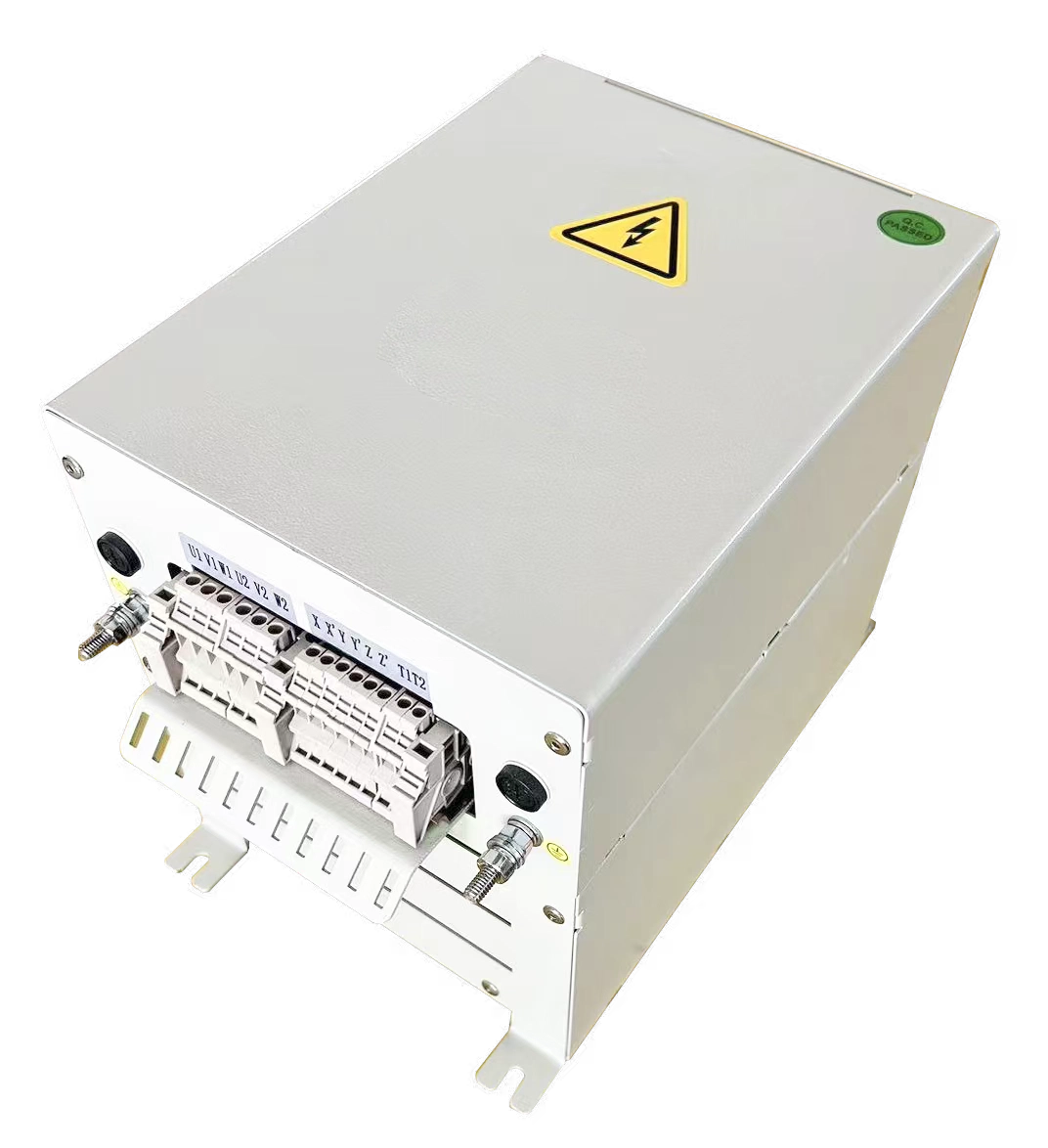
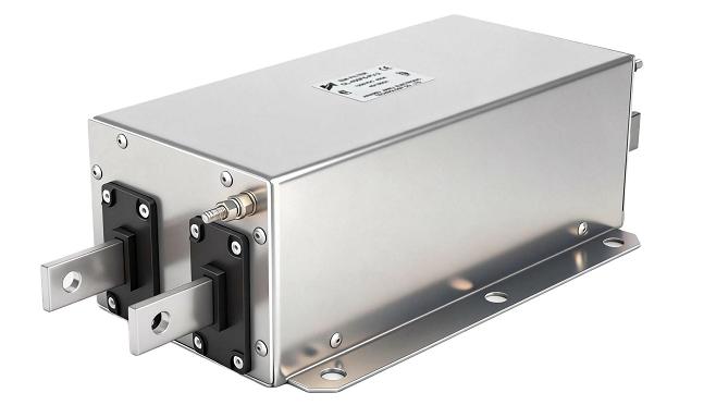
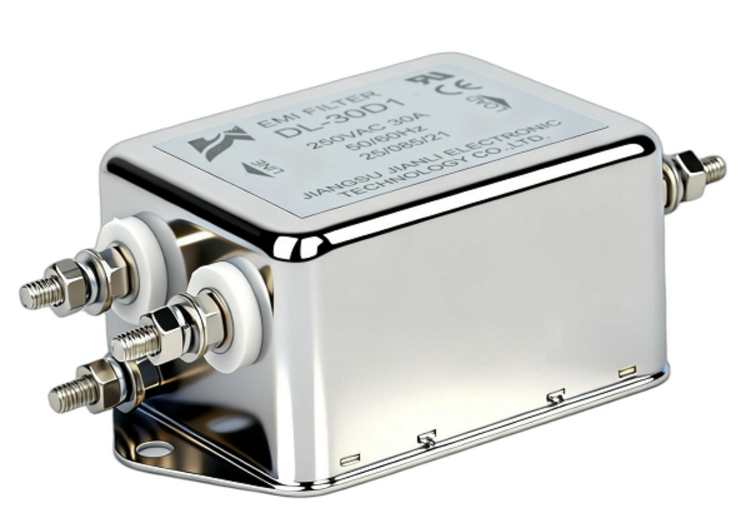
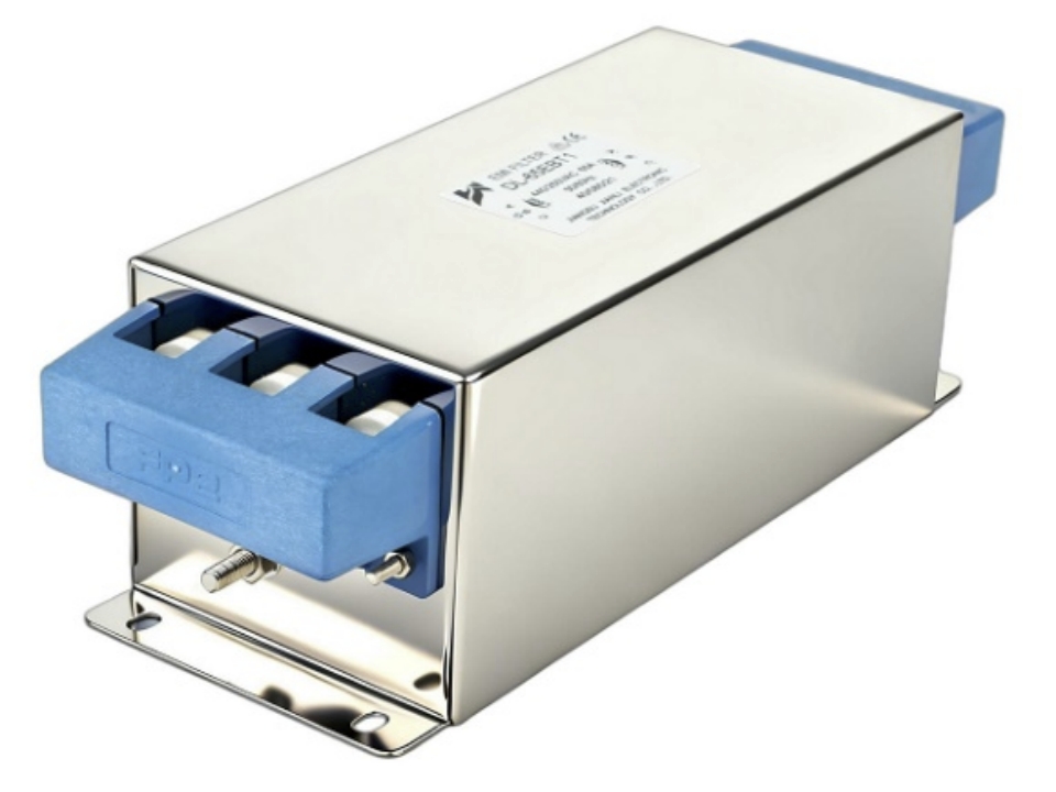
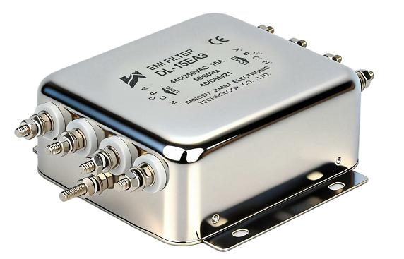
A DC filter for PV inverters suppresses conducted EMI noise on the DC bus, protects switching components, and ensures compliance with IEC 61000-6-3 and CISPR 11. Without it, high-frequency switching transients propagate through PV strings, degrading system reliability and failing EMC certification.
1. The EMI Problem on the DC Side of PV Inverters
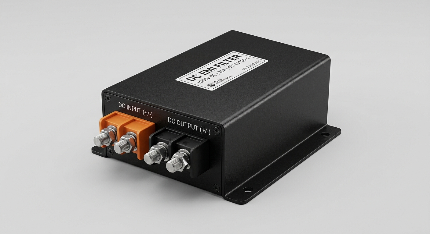
Modern PV inverters use IGBT or SiC MOSFET switching at frequencies of 16–100 kHz. Each switching event generates broadband conducted EMI noise across 150 kHz–30 MHz.
Two primary noise modes exist:
- Common-mode (CM) noise: Flows through parasitic capacitance between PV panel frames and ground. Typical CM impedance in a 10 kW string system is 50–200 nF.
- Differential-mode (DM) noise: Propagates along the positive and negative DC conductors. Generated directly by PWM switching voltage ripple.
Why the DC side is critical:
- PV cable runs of 10–100 m act as unintentional antennas.
- No galvanic isolation exists in transformerless inverter topologies (H5, HERIC, NPC).
- Leakage current through panel-to-ground capacitance exceeds 300 mA in unfiltered systems, triggering RCD faults.
| Noise Type | Frequency Range | Primary Path | Risk |
|---|---|---|---|
| Common-mode | 150 kHz – 10 MHz | PV frame → PE conductor | RCD tripping, radiated EMI |
| Differential-mode | 150 kHz – 30 MHz | DC+ / DC− conductors | Conducted emissions failure |
| Switching ripple | 16–100 kHz (fund.) | DC bus capacitors | Capacitor stress, THD |
2. What Is a DC Filter for PV and How Does It Work?
A DC-side EMI filter for solar inverters is a passive LC network inserted between the PV string combiner and the inverter DC input terminals.
2.1 Filter Topology and Components
Standard DC EMI filter architecture includes:
- Common-mode choke (CMC): Wound on a nanocrystalline or ferrite toroidal core; inductance 1–10 mH; attenuates CM current by 40–60 dB.
- X-capacitors (CX): Connected across DC+ and DC−; values 0.1–4.7 µF; suppress DM noise.
- Y-capacitors (CY): Connected from DC+ and DC− to PE; values 4.7–47 nF; divert CM current to ground.
- Discharge resistors: Mandatory per IEC 62368-1; discharge CX below 60 V within 1 second.
2.2 Insertion Loss Performance
| Filter Stage | Attenuation at 150 kHz | Attenuation at 1 MHz | Attenuation at 10 MHz |
|---|---|---|---|
| Single-stage LC | 20–30 dB | 35–45 dB | 40–50 dB |
| Two-stage LC | 35–50 dB | 55–65 dB | 60–70 dB |
| Three-stage LC | 50–65 dB | 70–80 dB | 75–85 dB |
Design constraints specific to PV DC filters:
- Rated voltage: 600 V, 1000 V, or 1500 V DC (IEC 62109-1 compliant).
- Leakage current must remain below 3.5 mA per IEC 60950 / UL 1741 requirements.
- Operating temperature range: −40°C to +85°C for outdoor enclosure compatibility.
3. Where Is a DC Filter Installed in a PV System?
Installation position determines filter effectiveness and protection scope.
Recommended installation points:
- Position A – String combiner output: Filters noise from multiple PV strings before the DC cable run. Protects long cable segments acting as antennas.
- Position B – Inverter DC input terminals: Provides last-stage filtering immediately before the switching stage. Most effective for inverter-level EMC compliance testing.
- Position C – Inside inverter enclosure: Used by OEM inverter manufacturers integrating the DC EMI filter as a built-in subsystem.
System topology impact:
| Inverter Topology | CM Noise Level | Recommended Filter Type |
|---|---|---|
| Full-bridge (transformer) | Low–Medium | Single-stage DM filter |
| H5 / HERIC (transformerless) | High | Two-stage CM+DM filter |
| NPC / T-type (three-level) | Medium–High | Two-stage CM+DM filter |
| Three-phase string inverter | High | Three-stage filter, 3-line DC |
Cable length rule of thumb: For every 10 m of unshielded DC cable added beyond the filter, CM noise re-injection increases by approximately 3–6 dB. Filter placement at the inverter input is always preferred over remote placement.
4. How to Choose a DC Filter for a PV Inverter
Selecting the correct PV inverter DC filter requires matching five electrical parameters to the system specification.
4.1 Electrical Rating Checklist
- DC voltage rating: Must exceed maximum open-circuit string voltage (Voc × 1.25 safety factor). For 1500 V systems, select 1800 V-rated components.
- Continuous current rating: Match to maximum DC input current (Isc × 1.25). A 20 A string requires a 25 A-rated filter.
- Leakage current budget: Y-capacitor total leakage must not exceed system RCD trip threshold (typically 30 mA or 300 mA depending on protection class).
4.2 EMC Performance Criteria
- Target insertion loss of ≥40 dB at 150 kHz (CISPR 11 Class B limit).
- Verify filter performance with impedance-matched source/load (50 Ω/50 Ω LISN test per CISPR 17).
- Request third-party insertion loss curves; manufacturer self-reported data is insufficient for compliance design.
4.3 Environmental and Mechanical Criteria
- IP rating: IP54 minimum for string combiner mounting; IP65 for direct outdoor exposure.
- Enclosure material: UV-stabilized polycarbonate or powder-coated aluminum.
- Certification marks: UL 1741, IEC 62109-1, CE marking for target markets.
5. Can a DC EMI Filter Improve PV Inverter EMC Performance?
Yes — measurably and verifiably. A properly specified DC-side EMI filter for solar inverters directly reduces conducted emissions at the AC output port through impedance decoupling.
Mechanism: DC-side CM noise couples into the inverter ground plane and re-emerges at the AC output. A DC filter with 40 dB CM attenuation reduces AC-port conducted emissions by 15–25 dB in the 150 kHz–500 kHz band.
Compliance impact:
- CISPR 11 Class B quasi-peak limit at 150 kHz: 66 dBµV.
- Typical unfiltered transformerless inverter: 85–95 dBµV at 150 kHz.
- After two-stage DC EMI filter: 62–70 dBµV — within or near the Class B limit.
Secondary performance benefits:
- Reduces switching stress on DC bus electrolytic capacitors, extending MTBF by 20–35%.
- Lowers ground leakage current, reducing false RCD trips in residential installations.
- Decreases radiated emissions from DC cable harnesses, supporting full-system EMC compliance.
6. Real-World Application Scenarios
Scenario 1 — Residential rooftop system (5–10 kW, transformerless H5 inverter):
- Problem: System fails CISPR 11 Class B at 150–500 kHz by 18 dB.
- Solution: Two-stage DC filter (CMC + X/Y capacitors), 1000 V / 15 A rated.
- Result: 22 dB reduction in conducted emissions; CE certification achieved.
Scenario 2 — Commercial rooftop system (100 kW, three-phase string inverters):
- Problem: Repeated RCD nuisance tripping due to 450 mA leakage current.
- Solution: DC filter with controlled Y-capacitor leakage (<2 mA per phase).
- Result: Leakage reduced to 18 mA total; zero RCD trips over 12-month monitoring.
Scenario 3 — Utility-scale ground-mount (1500 V DC bus, central inverter):
- Problem: Radiated EMI interfering with on-site SCADA communication at 433 MHz.
- Solution: Three-stage DC filter integrated at combiner box output.
- Result: SCADA packet error rate reduced from 12% to 0.3%.
FAQ: DC Filter for PV Systems
Q1: Why does a PV inverter need a DC filter?
To suppress conducted EMI from high-frequency PWM switching before it propagates through DC cables.
Q2: Where is a DC filter installed in a PV system?
At the inverter DC input terminals or string combiner output, depending on system layout.
Q3: What type of EMI can a DC filter for PV reduce?
Both common-mode (150 kHz–10 MHz) and differential-mode (150 kHz–30 MHz) conducted noise.
Q4: How do you choose a DC filter for a PV inverter?
Match voltage rating, current rating, leakage budget, and required insertion loss to system specs.
Q5: Can a DC EMI filter improve PV inverter EMC performance?
Yes — a two-stage filter typically reduces conducted emissions by 20–40 dB at 150 kHz.
Q6: What standards apply to DC filters in PV systems?
IEC 62109-1, CISPR 11, IEC 61000-6-3, UL 1741, and IEC 61000-4-5 for surge immunity.
Q7: What is the typical leakage current of a PV DC filter?
Below 3.5 mA per IEC 60950; Y-capacitor selection controls this parameter directly.
Q8: Do transformerless inverters need stronger DC filtering than transformer-based types?
Yes — absence of galvanic isolation increases CM noise by 15–25 dB, requiring two- or three-stage filters.
Conclusion
A DC filter for PV systems is not an optional accessory — it is a fundamental EMC engineering requirement for any transformerless inverter design operating above 10 kHz switching frequency. The combination of CM chokes, X-capacitors, and controlled Y-capacitors provides 40–80 dB attenuation across the 150 kHz–30 MHz conducted emissions band.
Key engineering takeaways:
- Specify filter voltage rating at 1.25× Voc; current rating at 1.25× Isc.
- Target ≥40 dB insertion loss at 150 kHz for CISPR 11 Class B compliance.
- Limit total Y-capacitor leakage to stay within RCD protection thresholds.
- Validate with CISPR 17 LISN testing, not manufacturer insertion loss curves alone.
Engineers designing or procuring DC EMI filters should request full insertion loss data, third-party certification documentation, and confirm operating temperature ratings before system integration.
References and Standards
- CISPR 11:2015+AMD1:2016 — Industrial, scientific, and medical equipment: Radio-frequency disturbance characteristics.
- IEC 61000-6-3:2020 — Electromagnetic compatibility: Emission standard for residential environments.
- IEC 62109-1:2010 — Safety of power converters for use in photovoltaic power systems.
- IEC 61000-4-5:2017 — Surge immunity test.
- UL 1741:2021 — Standard for inverters, converters, controllers and interconnection system equipment for use with distributed energy resources.
- CISPR 17:2011 — Methods of measurement of the suppression characteristics of passive EMC filtering devices.
- Kempski, A. et al. (2020). “Common-mode conducted EMI in photovoltaic inverters.” IEEE Transactions on Power Electronics, 35(8), 8013–8025.
- Ran, L. et al. (2014). “Conducted electromagnetic emissions in inverter-driven systems.” IEEE Transactions on Power Electronics, 29(10), 5283–5291.