
Abstract
As photovoltaic installations scale from rooftop arrays to multi-megawatt utility projects, electromagnetic interference has emerged as one of the most persistent—and underestimated—threats to system reliability. Inverter switching transients, long DC cable runs, and inadequate grounding create a complex noise environment that degrades equipment performance, triggers nuisance shutdowns, and jeopardizes grid-connection approvals.
DC filters for PV are purpose-engineered to suppress this conducted and radiated noise before it propagates through the DC bus. Unlike generic industrial EMI filters, photovoltaic-specific designs account for the unique characteristics of solar arrays: unidirectional current flow, wide voltage swings from 600 V to 1500 V, and outdoor exposure across extreme temperature cycles.
This article provides procurement managers and system integrators with a structured technical evaluation of PV DC EMI filters—covering noise attenuation mechanisms, critical selection parameters, applicable compliance standards, and a quantified return-on-investment perspective. The goal is straightforward: to give you the technical foundation needed to specify the right filter, verify its compliance credentials, and justify the capital expenditure against the real cost of unresolved EMI.
1. Why PV Systems Generate EMI — And Why It Matters
1.1 Common EMI Sources in DC-Side PV Systems
The DC side of a photovoltaic installation is far from electrically quiet. Three primary mechanisms drive conducted EMI:
Inverter switching noise is the dominant source. Modern string and central inverters use IGBT or SiC MOSFET switches operating at frequencies between 8 kHz and 50 kHz. Each switching event generates voltage transients with rise times under 100 ns, producing broadband harmonic content that extends well into the 30 MHz range. This high-frequency noise couples directly onto the DC bus and propagates back toward the array.
Long DC cable runs act as antennas. In utility-scale ground-mount systems, DC home-run cables routinely span 100–300 meters between string combiner boxes and the inverter skid. At these lengths, cables efficiently radiate conducted noise and simultaneously pick up external interference, creating a bidirectional EMI pathway.
Ground loop currents arise from the parasitic capacitance between PV module frames and the earth. In transformerless inverter topologies—now the industry standard for efficiency reasons—there is no galvanic isolation between the DC bus and ground. This allows common-mode leakage currents to circulate through the grounding network, injecting low-frequency noise into monitoring equipment, communication buses, and protective relay circuits.
1.2 Business Impact of Unresolved EMI on PV Installations
For procurement decision-makers, EMI is not merely a technical nuisance—it translates directly into measurable financial exposure:
- Equipment malfunction and premature failure: Conducted noise accelerates insulation degradation in DC cables and causes spurious trips in string-level monitoring devices, increasing replacement frequency.
- Communication system interference: SCADA, power-line communication (PLC), and RS-485 Modbus networks sharing the same cable tray as DC wiring are highly susceptible to inverter-generated harmonics, leading to data loss and delayed fault detection.
- Regulatory non-compliance: Grid operators in the EU, North America, and Australia enforce EMC limits under standards such as IEC 61000-3-2 and EN 55011. A system that fails conducted emissions testing faces costly redesign, retesting fees, and delayed commissioning—sometimes by months.
- Warranty and insurance risk: Several inverter manufacturers explicitly state that EMI-related failures caused by inadequate filtering are excluded from warranty coverage, shifting liability entirely to the EPC contractor or asset owner.
The aggregate cost of a single EMI-related commissioning failure on a 10 MW project—including retesting, downtime, and engineering rework—typically ranges from $50,000 to $200,000, dwarfing the cost of correctly specified DC filters installed from the outset.
2. How DC Filters for PV Work — Technical Principles & Key Specifications
2.1 Filtering Topology and Noise Attenuation Mechanism
PV DC EMI filters employ a combination of common-mode (CM) and differential-mode (DM) filtering stages to address the two distinct noise propagation paths present on the DC bus.
Common-mode filtering uses a toroidal CM choke wound with both the positive and negative DC conductors passing through the same core. Because load current flows in opposite directions through the two windings, it cancels magnetically and the choke presents no impedance to DC power flow. However, CM noise—which flows in the same direction on both conductors relative to earth—sees the full inductance of the choke, typically 1–10 mH, providing substantial attenuation above 150 kHz. CM capacitors (Y-capacitors) connected from each conductor to the protective earth (PE) provide a low-impedance return path for high-frequency noise, completing the LC filter network.
Differential-mode filtering targets noise that appears between the positive and negative conductors. DM inductors (or the leakage inductance of the CM choke) combined with X-capacitors across the DC bus form a second-order low-pass filter. Together, CM and DM stages achieve insertion loss values of 40–80 dB across the 150 kHz to 30 MHz band that regulators scrutinize most closely.
The net result is a dramatically cleaner DC bus: high-frequency switching harmonics are reflected back toward the inverter or shunted to earth before they can propagate to the array, communication systems, or the AC grid through parasitic coupling.
2.2 Critical Specifications for PV DC Filter Selection
Selecting the wrong filter is as problematic as using no filter at all. The following parameters define a fit-for-purpose specification:
| Parameter | Typical Range | Selection Guidance |
|---|---|---|
| Rated Voltage (Vdc) | 600 V / 1000 V / 1500 V | Match to system maximum open-circuit voltage (Voc × 1.25 safety factor) |
| Rated Current (A) | 16 A – 1200 A | Size to maximum DC string or combiner output current |
| Insertion Loss (dB) | 40–80 dB @ 150 kHz–30 MHz | Higher dB required for proximity to sensitive equipment |
| Leakage Current (mA) | < 3.5 mA (TN) / < 1 mA (IT) | Governed by IEC 60990 and local grid codes |
| Operating Temperature | −40 °C to +85 °C | Critical for outdoor combiner box or tracker-mounted installations |
| IP Rating | IP54 minimum / IP65 for outdoor | Confirm enclosure class matches installation environment |
| Certifications | CE, IEC 62109, UL 1741 | Mandatory for market access; verify test reports, not just markings |
Leakage current deserves particular attention in transformerless PV systems. Excessive PE leakage can trigger residual current devices (RCDs) and violate grid-connection agreements. Filters designed specifically for PV applications limit leakage through careful Y-capacitor sizing—a compromise not found in repurposed industrial filters.
3. Compliance Standards & Certification Requirements
3.1 Applicable EMC Standards for PV DC Filters
PV DC filters must satisfy requirements drawn from multiple overlapping standards frameworks:
- IEC 61000-6-2 / IEC 61000-6-4: Generic immunity and emission standards for industrial environments, forming the baseline EMC requirement for most grid-tied PV equipment.
- EN 55011 (CISPR 11): Defines conducted and radiated emission limits for industrial, scientific, and medical equipment. Class A limits (quasi-peak and average) apply to utility-scale PV plants; residential or commercial rooftop systems adjacent to sensitive receivers may need to meet the tighter Class B limits.
- IEC 62109-1 / IEC 62109-2: The primary safety standard for power converters used in PV systems, covering inverters and associated DC-side components including filters. Compliance is mandatory for CE marking in Europe and referenced by Australian and other national standards.
- UL 1741 / IEEE 1547: Applicable for North American grid interconnection approvals; EMI filter components must be rated and tested to UL standards when specified by the Authority Having Jurisdiction (AHJ).
3.2 How to Verify Filter Compliance Before Procurement
A CE marking on the product label is a starting point, not a conclusion. Rigorous procurement due diligence should include:
- Request the full test report, not just the Declaration of Conformity (DoC). Confirm that the test was conducted by an accredited third-party laboratory (IECEE CB Scheme members or ILAC-recognized labs) and that the filter was tested at its rated voltage and current—not at reduced conditions.
- Check the insertion loss test frequency range: Verify that measurements cover 150 kHz to 30 MHz per CISPR 17 methodology. Some suppliers report insertion loss only at spot frequencies that flatter the product’s performance curve.
- Confirm leakage current measurement method: IEC 60990 Figure 4 network (touch current) is the relevant measurement circuit for PV applications—not the simplified resistive method sometimes used for industrial equipment.
- Validate IP rating: Request the IP test certificate, not just the datasheet claim. IP65 and IP67 ratings require distinct test procedures; confirm which applies to the terminal entry points, not just the enclosure body.
4. Real-World Applications & Commercial Value
4.1 Typical Installation Scenarios and Performance Results
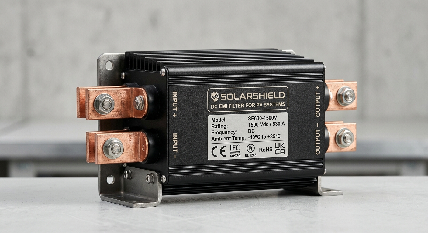
Utility-scale ground-mount systems represent the highest-stakes EMI environment. In a documented 50 MW project where central inverters were generating conducted emissions 15–22 dB above EN 55011 Class A limits, installation of 1000 Vdc / 630 A DC filters at each inverter DC input reduced conducted emissions to 8–12 dB below the limit across the 150 kHz–30 MHz band—bringing the installation into compliance without inverter firmware modifications.
Commercial and industrial rooftop installations face a different challenge: proximity to sensitive IT infrastructure, building management systems, and tenant communications equipment. In these environments, PV system noise reduction is not just a grid-code requirement but a tenant-relations and liability issue. String-level DC filters rated at 1000 Vdc / 32–63 A have consistently demonstrated 30–50 dB attenuation at the inverter switching frequency harmonics most likely to interfere with Wi-Fi and cellular repeater systems co-located on the same roof structure.
Hybrid storage systems combining PV arrays with battery energy storage introduce additional EMI complexity: bidirectional DC/DC converters generate switching noise in both charge and discharge modes. Filters installed on the DC bus between the PV combiner and the hybrid inverter have shown measurable improvement in battery management system (BMS) communication reliability, reducing CAN bus error rates by over 60% in field measurements.
4.2 ROI Analysis — Cost of Filter vs. Cost of EMI Failure
The financial case for DC EMI filters is asymmetric and compelling:
| Cost Category | Typical Value |
|---|---|
| DC filter unit cost (1000 V / 100 A) | $150 – $400 |
| EMC retest after commissioning failure | $8,000 – $25,000 |
| Project delay penalty (per week, 10 MW) | $15,000 – $40,000 |
| Inverter warranty claim denial (EMI-related) | $5,000 – $30,000 per unit |
| SCADA communication fault investigation | $2,000 – $10,000 |
For a 5 MW commercial project using 20 string inverters, specifying DC filters adds approximately $6,000–$12,000 to the DC BOS budget—less than 0.1% of total installed cost. A single post-commissioning EMC failure easily exceeds this figure by a factor of five to ten. The filter investment is not a premium; it is risk mitigation with a calculable payback period measured in weeks, not years.
FAQ — Procurement Decision Checklist
Q1: What DC voltage and current ratings should I specify for a 1500 V utility-scale system?
Specify a filter with a continuous DC voltage rating of at least 1500 Vdc and apply a 1.25× safety multiplier to your maximum string current when selecting the current rating. For a 1500 V / 1000 A combiner output, a 1500 Vdc / 1250 A rated filter provides the appropriate derating margin for long-term thermal reliability.
Q2: How do I confirm that a DC EMI filter meets the leakage current limits required by my local grid-connection standard?
Request the IEC 60990 Figure 4 touch-current test report from the supplier. Cross-reference the measured leakage current value against your grid operator’s specific limit—typically < 300 mA for utility systems and < 30 mA for systems with RCD protection. Do not rely on calculated estimates based on Y-capacitor values alone.
Q3: Can a single DC filter model cover both string inverter and central inverter applications?
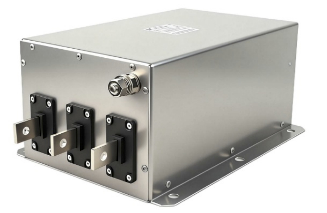
Generally, no. String inverter applications require lower current ratings (16–63 A) with emphasis on compact form factor and IP65 outdoor ratings. Central inverter applications demand high-current designs (400–1200 A) with bus-bar terminations and forced-air or liquid cooling options. Specifying a single SKU across both topologies results in either over-engineering costs or inadequate attenuation performance.
Conclusion
Electromagnetic interference on the DC side of photovoltaic systems is a quantifiable engineering problem with a proven, cost-effective solution. DC filters for PV deliver measurable noise attenuation—typically 40–80 dB across the critical 150 kHz to 30 MHz band—while addressing the leakage current constraints unique to transformerless solar architectures.
The procurement decision should be driven by three priorities: selecting the correct voltage and current ratings for your specific system architecture, verifying compliance credentials through third-party test documentation rather than self-declared certifications, and evaluating filter cost against the full financial exposure of an EMI-related commissioning failure or warranty dispute.
For system integrators and EPC contractors working under tight commissioning schedules and grid-connection timelines, specifying compliant DC EMI filters at the design stage is the lowest-risk, highest-return investment available on the DC BOS budget. Contact our technical team to receive a specification checklist tailored to your project voltage class and installation environment, or request sample units for pre-commissioning EMC validation testing.