
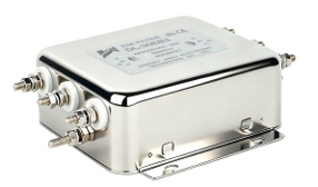
A DC filter suppresses high-frequency switching noise on the photovoltaic input bus, prevents common-mode and differential-mode interference from propagating through the inverter, and is a prerequisite for IEC 61000-series EMC compliance in grid-tied systems.
1. The EMC Problem on the DC Side of PV Inverters
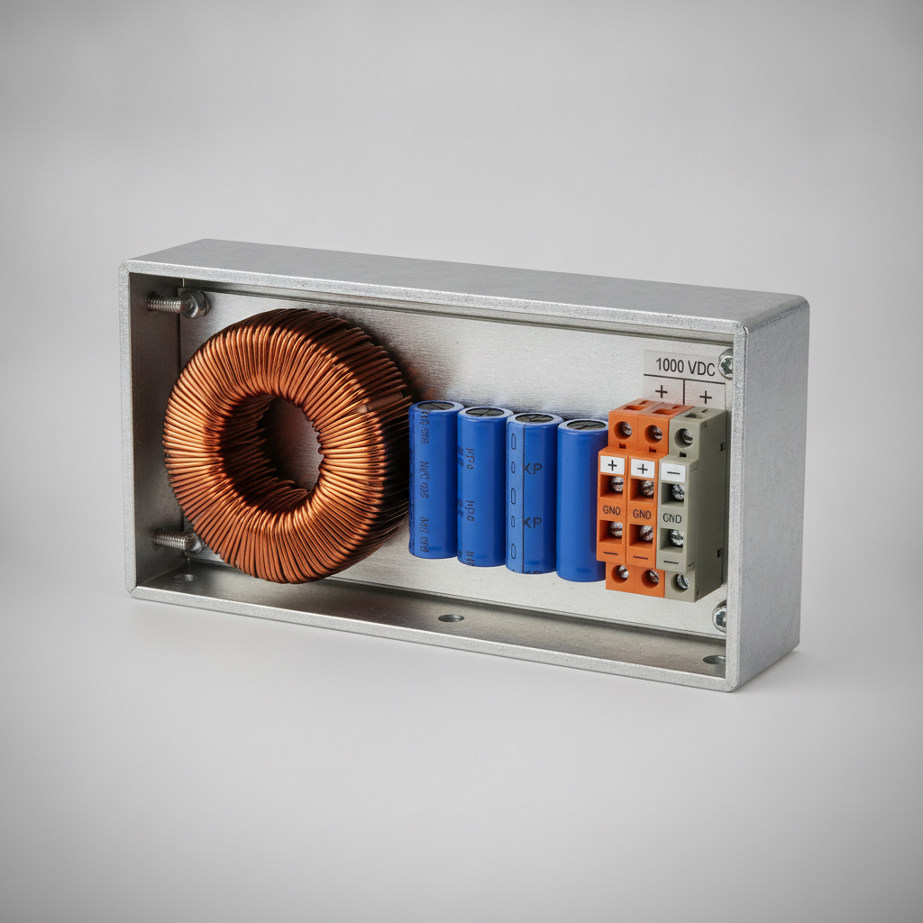
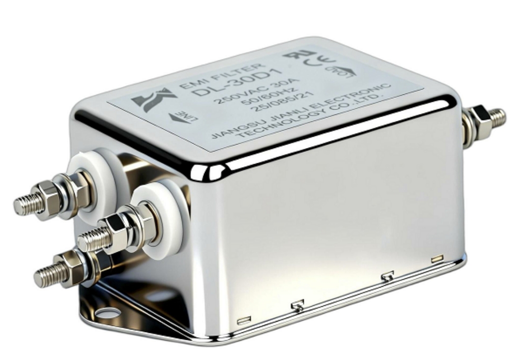
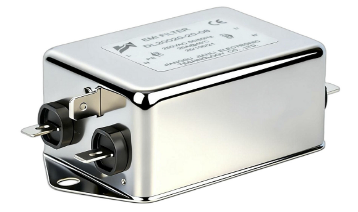
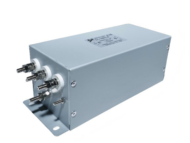
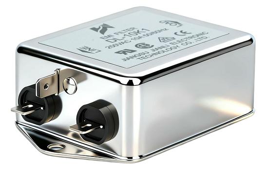
Here is the high-resolution, photorealistic B2B industrial image of the DC filter module:
Modern string and central inverters switch at 16–100 kHz using SiC or IGBT devices. Each switching event injects broadband conducted emissions onto the DC cable connecting the PV array to the inverter input.
Two interference modes are generated simultaneously:
- Common-mode (CM) noise: Current flows from DC conductors through stray capacitance to protective earth (PE). In transformerless inverters, this directly drives leakage current through the PV module frames.
- Differential-mode (DM) noise: Voltage ripple appears between the positive and negative DC rails, stressing capacitors and degrading MPPT accuracy.
Why the DC side is the critical injection point:
- PV cable runs of 10–100 m act as unintentional antennas above 150 kHz.
- The DC bus lacks the inherent galvanic isolation present on the AC output in transformer-based designs.
- Without a photovoltaic EMC filter at the inverter input, conducted emissions routinely exceed CISPR 11 Class B limits by 15–30 dB in the 150 kHz–30 MHz band.
| Interference Parameter | Typical Unfiltered Value | IEC/CISPR Limit | Excess |
|---|---|---|---|
| CM conducted emission @ 500 kHz | 85 dBμV | 56 dBμV | +29 dB |
| DM ripple voltage @ fsw | 4–8% of Vdc | <1% recommended | 4–8× |
| Leakage current (transformerless) | 150–400 mA | 300 mA (IEC 62109-1) | Borderline |
DC-side electromagnetic interference suppression is therefore not optional—it is a design constraint from the earliest schematic stage.
2. Switching Frequency Harmonics and Filter Attenuation Requirements
The switching frequency (fsw) and its harmonics define the filter’s insertion loss specification.
Harmonic profile of a 20 kHz IGBT inverter:
- Fundamental: 20 kHz — dominant DM component
- 2nd–5th harmonics: 40–100 kHz — significant CM and DM energy
- High-order harmonics: 150 kHz–30 MHz — primary CISPR 11 compliance band
Required attenuation by frequency band:
| Frequency Range | Noise Source | Required Attenuation |
|---|---|---|
| 20–100 kHz | Switching fundamental + harmonics | 40–60 dB |
| 150–500 kHz | Conducted emissions (CISPR 11 start) | 50–70 dB |
| 500 kHz–30 MHz | Radiated precursor / cable antenna | 30–50 dB |
Filter design implications:
- A single-stage LC filter provides ~40 dB/decade rolloff; two stages achieve ~80 dB/decade.
- SiC-based inverters switching at 60–100 kHz push the fundamental harmonic deeper into the CISPR band, requiring steeper rolloff and lower corner frequencies (fc = 5–15 kHz).
- The solar inverter DC filter must be co-designed with the DC cable impedance to avoid resonance peaks that amplify rather than attenuate noise.
3. DC Filter Topology Selection and Leakage Current Control
Topology choice directly determines leakage current magnitude—a critical safety and grid-code parameter.
Common DC filter topologies for PV inverters:
- L-C (single-stage): Simple, low cost; insertion loss limited to ~40 dB. Suitable for transformer-based inverters where CM path is broken.
- L-C-L (two-stage): Provides >70 dB attenuation; standard for transformerless string inverters above 5 kW.
- Common-mode choke + X/Y capacitors: Directly targets CM current path; Y-capacitors shunt CM noise to PE but increase leakage current if oversized.
How DC filter topology selection affects inverter leakage current:
- Y-capacitors (Cy) from DC rails to PE create a low-impedance CM return path.
- Each 100 nF of Cy at 50 Hz contributes approximately 1.6 mA of leakage current.
- IEC 62109-1 limits total leakage to 300 mA (continuous); IEC 62109-2 adds dynamic limits during grid faults.
- Optimal design uses Cy ≤ 150 nF per rail, combined with a high-inductance CM choke (1–10 mH) to achieve attenuation without exceeding leakage budgets.
Design trade-off matrix:
| Topology | CM Attenuation | DM Attenuation | Leakage Risk | Cost Index |
|---|---|---|---|---|
| Single-stage L-C | Low | Medium | Low | 1.0× |
| L-C-L two-stage | High | High | Medium | 1.8× |
| CM choke + Y-cap | Very High | Low | High if Cy > 200 nF | 1.5× |
| Hybrid (CM+LCL) | Very High | Very High | Controlled | 2.2× |
4. DC Filter Capacitor ESR and PV System Efficiency
Capacitor ESR (Equivalent Series Resistance) is the dominant loss mechanism in the inverter input filter design.
ESR impact on efficiency:
- A 100 μF film capacitor with ESR = 20 mΩ at 20 kHz dissipates P = I²·ESR.
- At 10 A ripple current: P = 100 × 0.020 = 2 W per capacitor.
- A 100 kW inverter with 12 input capacitors loses up to 24 W in ESR alone—0.024% efficiency penalty.
How DC filter capacitor ESR values impact PV system efficiency:
- Low-ESR polypropylene film capacitors (ESR < 5 mΩ) reduce thermal stress and extend capacitor lifetime beyond 100,000 hours at 70°C.
- Electrolytic capacitors (ESR = 50–200 mΩ) are unsuitable for high-ripple DC bus positions; they are acceptable only for bulk energy storage at low-frequency ripple.
- ESR also affects MPPT performance: high ESR increases DC bus voltage ripple, causing the MPPT algorithm to hunt across a wider voltage window, reducing energy harvest by 0.5–1.5% annually.
Capacitor selection criteria for DC filter positions:
- Film type: Polypropylene (PP) or Metallized Polypropylene (MKP)
- Voltage rating: ≥1.2 × Voc(STC) with 10% derating
- Ripple current rating: verified at fsw, not just 100 Hz
- Temperature coefficient: <200 ppm/°C for stable filter corner frequency
5. IEC Standards Governing DC Filter Requirements
Compliance with international standards is non-negotiable for grid-tied PV inverters sold in EU, Asia-Pacific, and North American markets.
Which IEC standards mandate DC filter requirements for grid-tied inverters:
- IEC 61000-6-2: Generic immunity standard for industrial environments — defines susceptibility thresholds the DC filter must protect against.
- IEC 61000-6-4 / CISPR 11: Conducted and radiated emission limits, 150 kHz–30 MHz — the primary standard driving DC filter insertion loss specifications.
- IEC 62109-1 / -2: Safety standard for power converters in PV systems — sets the 300 mA leakage current limit that constrains Y-capacitor sizing.
- IEC 61683: Efficiency measurement for PV inverters — indirectly penalizes high-ESR filter designs through mandatory efficiency reporting.
- EN 50178 / IEC 62477-1: Component-level standards for power electronic equipment, governing filter component ratings and creepage/clearance.
Regional compliance mapping:
| Market | Primary EMC Standard | Leakage Limit | Filter Certification |
|---|---|---|---|
| European Union | EN 61000-6-4 + CE | 300 mA | CE marking required |
| China | GB/T 19939 | 300 mA | CQC / CGC |
| North America | FCC Part 15 Class B | 500 mA | UL 1741 |
| Australia | AS 4777.2 | 300 mA | RCM |
6. Real-World Application Scenarios
Scenario A: 100 kW Rooftop Commercial PV System
- Problem: String inverters failed CISPR 11 Class B at 500 kHz by 22 dB during pre-compliance testing.
- Solution: Two-stage LCL DC filter with 3 mH CM choke and 150 nF Y-capacitors per rail.
- Result: Emissions reduced to 8 dB below limit; leakage current held at 180 mA.
Scenario B: 1 MW Ground-Mount Utility System with Long DC Cable Runs
- Problem: 80 m DC cables resonated with single-stage filter at 85 kHz, amplifying noise.
- Solution: Hybrid CM choke + damped LCL topology with parallel RC snubber on the second inductor.
- Result: Resonance peak eliminated; MPPT efficiency improved by 1.1% annually.
Scenario C: SiC-Based 50 kW Inverter at 80 kHz Switching Frequency
- Problem: High fsw pushed fundamental harmonic to 80 kHz, directly inside CISPR measurement band.
- Solution: Low-corner-frequency (8 kHz) two-stage filter using MKP capacitors with ESR < 3 mΩ.
- Result: Full CISPR 11 Class A compliance; filter loss < 0.03% of rated power.
FAQ: DC Filter in PV Inverters
Q: How does DC-side common-mode noise degrade PV inverter EMC compliance?
CM noise drives leakage current through stray capacitance, exceeding CISPR 11 conducted emission limits above 150 kHz.
Q: What switching frequency harmonics require DC filter attenuation?
Harmonics from fsw up to the 15th order (typically 150 kHz–1.5 MHz) fall within the CISPR 11 mandatory measurement band.
Q: How do DC filter capacitor ESR values impact PV system efficiency?
High ESR increases ripple current losses and MPPT hunting, reducing annual energy yield by up to 1.5%.
Q: Which IEC standards mandate DC filter requirements for grid-tied inverters?
CISPR 11 / IEC 61000-6-4 for emissions; IEC 62109-1 for leakage current; IEC 62477-1 for component ratings.
Q: How does DC filter topology selection affect inverter leakage current?
Y-capacitor sizing is the primary control variable; each 100 nF adds ~1.6 mA leakage at 50 Hz.
Q: Can a DC filter be added after inverter installation?
Retrofit is possible but suboptimal; impedance mismatch with existing cable runs often requires custom damping networks.
Q: What is the typical insertion loss of a solar inverter DC filter?
A two-stage LCL design achieves 60–80 dB insertion loss at 500 kHz under matched impedance conditions.
Q: Why do SiC inverters require different DC filter designs than IGBT inverters?
Higher fsw (60–100 kHz) and faster dv/dt (>10 kV/μs) demand lower filter corner frequencies and higher-grade capacitor dielectrics.
Conclusion
A properly designed DC filter is the primary tool for achieving CISPR 11 compliance, controlling leakage current within IEC 62109-1 limits, and protecting MPPT efficiency in photovoltaic systems. Key engineering decisions—topology selection, Y-capacitor sizing, and capacitor ESR specification—must be resolved at the schematic stage, not as afterthoughts during pre-compliance testing.
Engineering recommendations:
- Specify filter corner frequency at ≤ fsw/4 to provide adequate attenuation margin.
- Use MKP film capacitors with ESR < 5 mΩ at all high-ripple DC bus positions.
- Validate leakage current budget before finalizing Cy values; target ≤ 200 mA headroom below the IEC 62109-1 limit.
- Perform impedance sweep of DC cable + filter network to identify and damp resonance peaks above 10 kHz.
For procurement teams and system integrators: request third-party insertion loss curves (not manufacturer simulations) and verify component ratings at operating temperature, not standard test conditions.
References and Standards
- IEC 61000-6-4:2018 — Electromagnetic compatibility, generic emission standard, industrial environment
- CISPR 11:2015+AMD1:2016 — Industrial, scientific and medical equipment, radio-frequency disturbance characteristics
- IEC 62109-1:2010 — Safety of power converters for use in photovoltaic power systems, Part 1
- IEC 62109-2:2011 — Safety of power converters, Part 2: inverters
- IEC 62477-1:2012 — Safety requirements for power electronic converter systems and equipment
- IEC 61683:1999 — Photovoltaic systems, power conditioners, procedure for measuring efficiency
- Kolar, J.W. et al., “PWM Converter Power Density Barriers,” IEEE Transactions on Power Electronics, 2017
- Heldwein, M.L., Kolar, J.W., “Impact of EMC Filters on the Power Density of Modern Three-Phase PWM Converters,” IEEE Transactions on Power Electronics, Vol. 24, No. 6, 2009