
Abstract
High-power EV charging stations concentrate fast-switching power electronics, long high-current cables, and sensitive control interfaces in a compact footprint. The result is pronounced electromagnetic interference (EMI) spanning conducted and radiated domains that can propagate into the grid, into the vehicle, and across site communications. Left unmanaged, EMI undermines charging uptime, complicates system-level EMC compliance, and elevates warranty risk. A DC Filter for EV is engineered specifically to attenuate common-mode (CM) and differential-mode (DM) noise on the DC bus of fast-charging and ultra-fast-charging systems, typically from 50 kW up to 350 kW+ per dispenser. This article details the filtering topologies, materials, and thermal design considerations that allow EV-grade DC filters to operate reliably at up to 1500 VDC and 600 A+, the regulatory context they serve, and the tangible commercial value they unlock for system integrators and OEMs—reduced redesign loops, faster certification, and robust field performance. We also provide a concise parameter comparison, deployment guidelines across CCS/CHAdeMO/GB/T architectures, and practical selection advice to resolve EMI hotspots without overspecifying hardware.
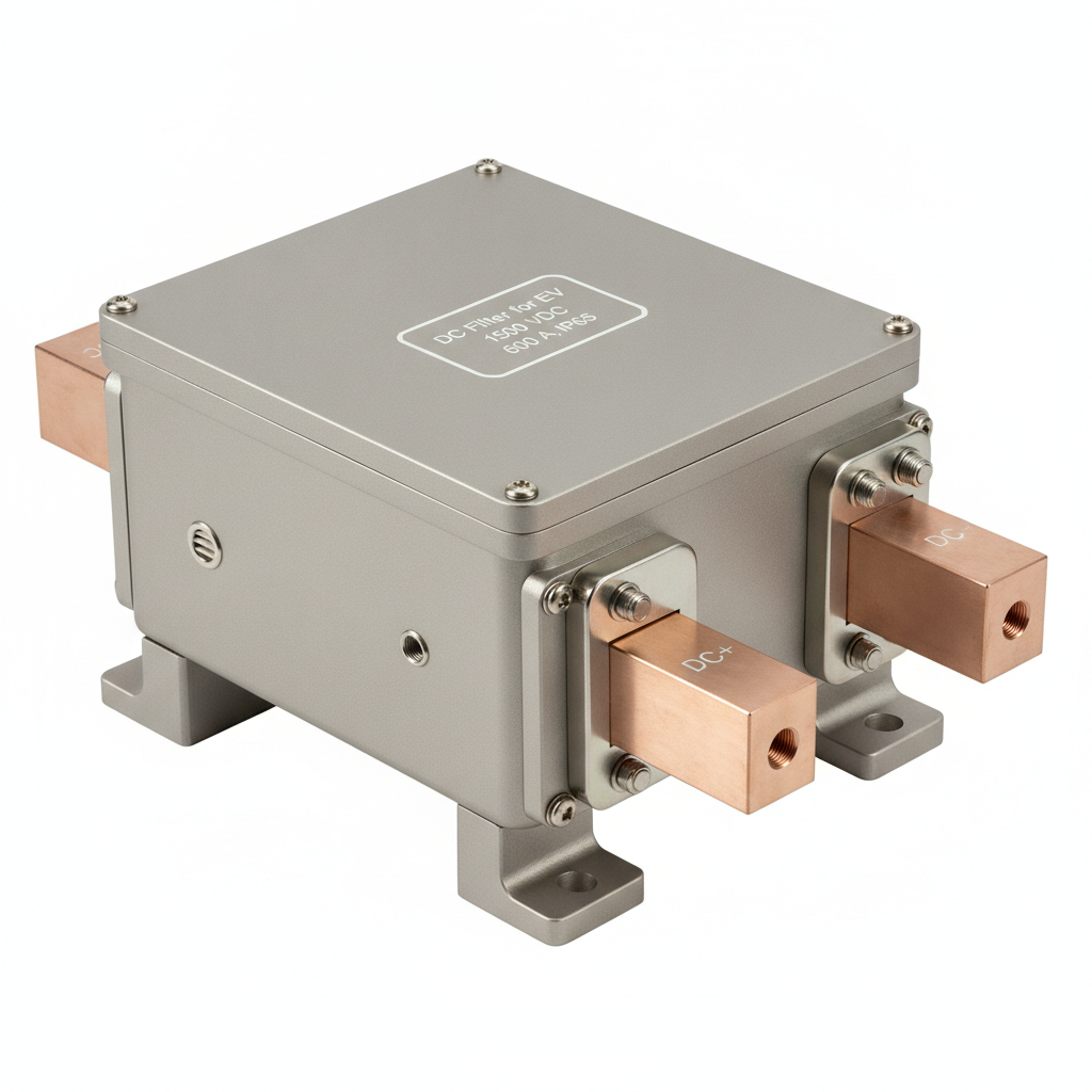
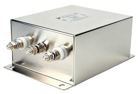
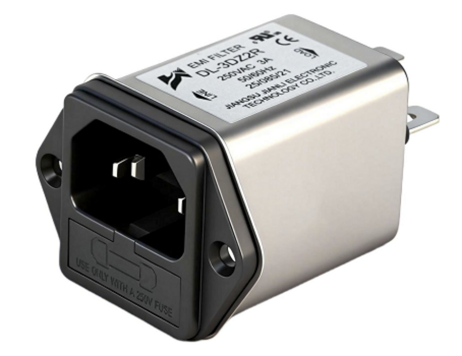
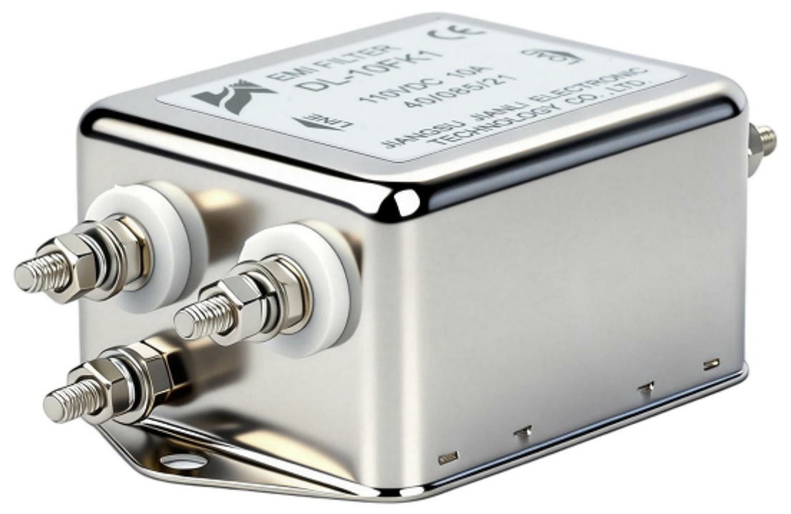
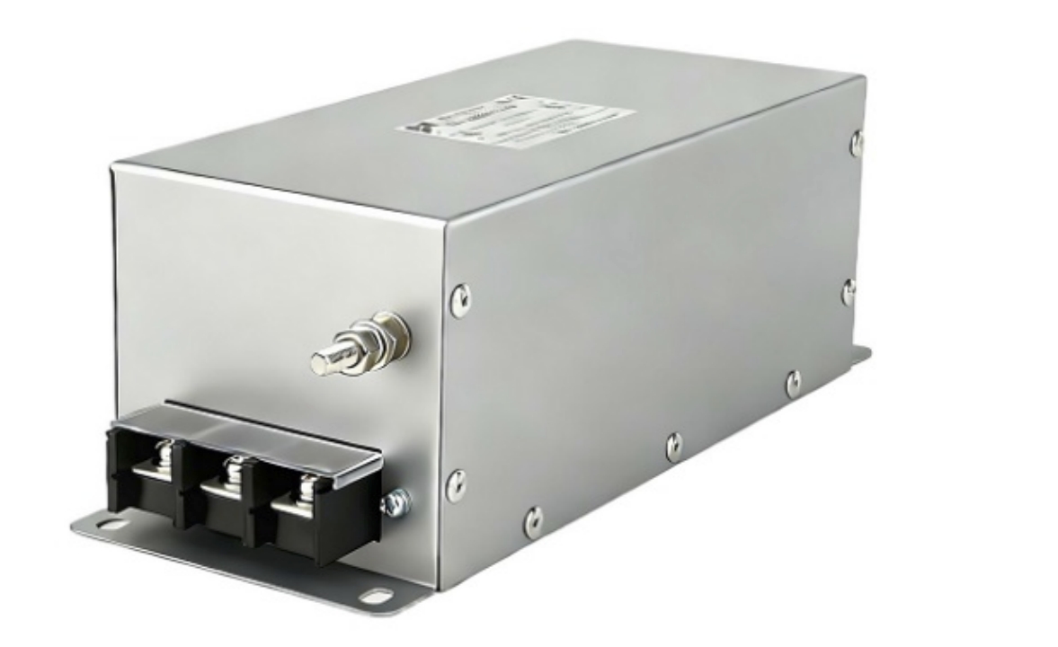
Here is the image of the high-power DC EMI filter for EV charging systems:
1. Why EMI Is a Critical Challenge in EV Charging Systems
1.1 Sources and Propagation of EMI in DC Charging Circuits
High-power EV chargers rely on multi-kilowatt power conversion stages using IGBT, SiC, or GaN switches. Switching edges in the tens of nanoseconds produce broadband noise from 150 kHz to hundreds of MHz. Key mechanisms include:
- Differential-mode (DM) noise: Voltage ripple and current ripple on the positive and negative DC bus conductors arising from PWM switching, rectifier stage commutation, and module interleaving beat frequencies.
- Common-mode (CM) noise: Coupled through parasitic capacitances (device drain-to-heat-sink, primary-to-secondary in isolated DC/DC stages) to chassis ground, flowing along cable shields and earth paths.
- Cable and enclosure coupling: Long output harnesses and liquid-cooled cables act as effective antennas; enclosure seams and bonding points create unintended return paths.
- Propagation paths:
- Vehicle side: Noise enters the vehicle’s BMS, OBC, and safety monitoring circuits via the DC inlet. CM noise can couple into shielded HV lines and low-voltage harnesses.
- Grid side: Conducted emissions travel back through the rectifier and into the AC mains, challenging site compliance, particularly in shared commercial/industrial feeders.
- Communication interfaces: High-frequency noise couples into CAN, PLC, Ethernet, or OCPP gateways through ground loops or insufficient segregation.
Without dedicated DC-side filtering, even well-designed power modules can exhibit unpredictable EMI signatures when integrated with real-world cable lengths and grounding schemes.
1.2 Consequences of Unfiltered EMI on EV Infrastructure
The impact of unmanaged EMI is both technical and commercial:
- Vehicle interoperability: DM ripple can destabilize battery management system readings; CM noise spikes can trigger vehicle-side protection, causing charge session aborts and perceived “charger faults.”
- Grid disturbance: Excessive conducted emissions elevate harmonics and high-frequency noise on the mains, risking penalties or failed site acceptance in regions with strict utility rules.
- Communication reliability: EMI can corrupt PLC-based communication on the power lines (e.g., for CCS), disrupt CAN diagnostics, or induce jitter on Ethernet links to payment and backend systems.
- Certification risk: Failing EMC pre-compliance forces chassis redesign, cable re-routing, and extended lab bookings—costly and time-consuming late-stage changes.
- Reliability and warranty: Recurrent spurious trips and thermal stress from high ripple currents erode component lifetime, increase service dispatches, and expand warranty exposure.
A DC Filter for EV addresses these issues at their source—the high-current DC bus—by providing targeted CM/DM attenuation tuned to the charger’s switching spectrum and site-specific cable harness characteristics.
2. How a DC Filter for EV Works: Technical Principles and Design Architecture
2.1 Core Filtering Topology and Component Selection
EV-grade DC EMI filters combine carefully tuned networks and materials to achieve wideband attenuation under high current and voltage stress:
- Topology:
- LC or π (C-L-C) networks: X-capacitors across the DC+ and DC− rails reduce DM ripple; the series inductor or differential choke provides high impedance at switching frequencies; the second capacitor bank stabilizes the residual ripple.
- Common-mode chokes: Two windings on a shared core present high impedance to CM currents while minimally affecting DC current. This is essential for suppressing radiated emissions motivated by long output leads.
- Capacitors:
- Film (polypropylene) capacitors with low ESR/ESL handle high ripple currents and deliver stable performance over temperature; DC filters may feature segmented banks to spread thermal load.
- Y-capacitors from DC rails to chassis ground provide CM shunting. Leakage current limitations and touch current considerations guide capacitance values, particularly for public EVSE.
- Magnetic cores:
- Nanocrystalline or high-permeability ferrites provide high inductance in compact volumes with low core loss at the relevant frequency bands (150 kHz–10 MHz+).
- Segmented winding and interleaving reduce parasitics, improving high-frequency attenuation without saturating under transient surges.
- High-frequency optimization:
- Damping resistors (RC snubbers) mitigate resonance peaks introduced by long cable inductance and filter capacitance.
- Layout discipline—short return paths, shield termination at one or both ends as appropriate, and minimized loop areas—is as critical as component values for real-world performance.
- Mechanical and materials durability:
- Tin-plated copper busbars with generous creepage/clearance align with 1000/1500 VDC platforms.
- Vibration-resilient potting or selective conformal coating (UL 94 V-0) protects internals against humidity, dust, and thermal cycling common in outdoor charging hubs.
In short, the DC Filter for EV is not a generic power-line filter; it is a purpose-built assembly balancing CM/DM performance, thermal headroom, and EVSE safety constraints.
2.2 Thermal Management and High-Current Handling in EV-Grade Filters
Continuous operation at hundreds of amps demands a thermal strategy that avoids temperature-driven drift and early aging:
- Current and voltage headroom:
- Typical designs support 400–600 A continuous at ambient temperatures up to 50–55°C, with short-term overload capability for dynamic charging profiles.
- Insulation systems designed for 1000–1500 VDC platforms ensure sufficient creepage/clearance and partial discharge margins for long service life.
- Heat management:
- Low-loss magnetic materials limit core heating; copper conduction paths are sized for minimal I2R losses.
- Passive conduction via thick baseplates to the charger backplate is common; high-power variants also integrate finned heatsinks or liquid-cooled cold plates.
- Environmental protection:
- IP54–IP65 enclosures shield against dust and water ingress; gaskets and breathable vents manage condensation.
- Corrosion-resistant housings (powder-coated aluminum or stainless steel) with robust mounting feet withstand depot and roadside installations.
The following table summarizes representative configurations to guide selection. Values are indicative and should be validated against project-specific EMI profiles.
| Model | Rated Voltage (VDC) | Rated Current (A) | Insertion Loss (dB @ freq) | CM/DM Attenuation Performance | Operating Temp (°C) | IP Rating | Applicable Standards (CCS/CHAdeMO/GB/T) | Mounting |
|---|---|---|---|---|---|---|---|---|
| EV-DF150 | 1000 | 300 | 30–50 dB (150 kHz–5 MHz); 20–30 dB (5–30 MHz) | CM: up to 55 dB; DM: up to 35 dB | -40 to +85 | IP54 | CCS, CHAdeMO, GB/T | Panel Mount |
| EV-DF300 | 1500 | 600 | 40–60 dB (150 kHz–10 MHz); 25–35 dB (10–30 MHz) | CM: up to 65 dB; DM: up to 40 dB | -40 to +85 | IP65 | CCS, GB/T | Panel Mount / Inline |
| EV-DF100 | 1000 | 150 | 25–45 dB (150 kHz–5 MHz); 18–25 dB (5–30 MHz) | CM: up to 50 dB; DM: up to 30 dB | -40 to +85 | IP54 | CCS, CHAdeMO | DIN Rail / Panel Mount |
Notes:
- Insertion loss is measured with a 50 Ω/50 Ω test setup; in-cabinet performance depends on cable lengths, bonding strategy, and enclosure geometry.
- CM performance typically governs radiated emissions improvement; DM governs conducted emissions margins.
3. Compliance Standards and Certification Requirements
3.1 Key EMC/EMI Regulations for EV Charging Equipment
DC fast chargers must satisfy EMC limits and immunity requirements across multiple jurisdictions. A DC Filter for EV directly supports the conducted emissions portion and indirectly improves radiated performance:
- IEC 61851 (EV conductive charging systems):
- Part 23 (DC EVSE) and Part 21 series address EMC requirements for EV charging equipment. Regional adoptions map to EN and GB/T frameworks.
- IEC 61000-6-4 (emission, industrial environments) and IEC 61000-6-2 (immunity):
- Often used when product-specific standards defer to generic industrial limits for conducted/radiated emissions and immunity.
- CISPR 32 (emission requirements for multimedia equipment) as referenced in some regional frameworks:
- Many EVSE certifications alternatively reference CISPR 11/EN 55011. The chosen path depends on local market acceptance; your filter must provide adequate margins from 150 kHz to 30 MHz conducted, and 30 MHz to 1 GHz radiated.
- GB/T 18487 (China EV charging):
- Includes EMC clauses aligned with the international framework; DC-side filtering helps achieve conducted emission limits on the DC output.
- UL/CE marking:
- UL 1283 (EMI filters) recognition may apply to the filter as a component; EVSE end-product certifications (e.g., UL 2202, UL 2231) evaluate the integrated system. CE marking involves EMC Directive 2014/30/EU and Low Voltage Directive 2014/35/EU compliance.
Designers should confirm the specific EMC path (CISPR class, measurement setups, and test limits) with their notified body or NRTL early in the project to size DC filtering appropriately.
3.2 How DC Filters Support System-Level EMC Certification
A properly engineered DC filter increases the likelihood of first-pass compliance and decreases the number of costly lab iterations:
- Conducted emission headroom:
- By delivering 30–60 dB attenuation in the critical 150 kHz–10 MHz band, the filter reduces peaks that otherwise exceed limits when long output leads and real vehicle loads are present.
- Radiated emission reduction:
- Strong CM attenuation lowers cable shield currents, often shrinking far-field hotspots near 100–300 MHz where harness resonances occur.
- Immunity benefits:
- Lower impedance to high-frequency disturbances on the DC bus improves system resilience when subjected to EFT/Burst and surge tests per IEC 61000-4 series.
- Pre-compliance strategy:
- Use LISNs and CDN setups with representative cable lengths, vehicle emulators, and chassis bonding. A DC filter with accessible test tabs and documented S-parameters simplifies iterative tuning.
- Vendors should provide insertion loss curves, SPICE/macromodels for DM/CM networks, dielectric withstand data, and CAD for mechanical integration.
- Documentation for OEM integration:
- Complete datasheets including creepage/clearance, leakage current, and thermal derating.
- Material declarations (RoHS/REACH), IP rating test reports, and component approvals (e.g., UL recognized chokes and capacitors).
- Quality certifications (ISO 9001, IATF 16949 where automotive-grade processes are requested) to support PPAP or supplier qualification audits.
The result: accelerated EMC sign-off, predictable lab outcomes, and reduced rework of enclosure, harness, and grounding.
4. Application Scenarios and Commercial Value
4.1 Deployment Use Cases Across Charging Architectures
A DC Filter for EV is a foundational element across varied EVSE topologies:
- 50–150 kW DC fast chargers:
- Often modular (e.g., 15–30 kW rectifier bricks in parallel). Interleaving helps but introduces beat frequencies. A DC filter at the combined DC bus provides uniform attenuation and decouples module-to-cable resonances.
- 350 kW+ ultra-fast chargers (HPC):
- Extremely high di/dt and long liquid-cooled cables amplify both DM and CM problems. Filters with nanocrystalline CM chokes and high-current film caps deliver needed suppression without excessive thermal rise.
- Charging hubs and multi-dispenser sites:
- Shared DC bus architectures benefit from a centralized filter upstream plus smaller point-of-load filters at each dispenser to control cable-specific resonances.
- Fleet depot charging:
- Mixed vehicle platforms (CCS, CHAdeMO, GB/T) and simultaneous sessions raise the noise floor. A robust DC filter mitigates cross-coupling between bays and supports stable site communications.
- Bidirectional V2G systems:
- With power flow reversal, the filter must be symmetrical and maintain attenuation for both charge and discharge modes. Attention to Y-cap values and control of CM currents is essential to keep PLC links robust.
Placement guidance:
- Position the DC filter close to the output of the isolated DC/DC stage, before the contactor and cable harness. Minimize loop area between filter and cable glands. Terminate cable shields per system policy (single-end vs both-end) to avoid CM loops.
4.2 Procurement and Integration Value for System Integrators
For procurement teams and system architects, the right DC filter directly influences project timelines and lifecycle cost:
- Lower EMC redesign costs:
- A validated filter with proven insertion loss in the target frequency bands avoids enclosure rework, cable rerouting, and feature compromises late in development.
- Platform flexibility:
- Selecting a 1500 VDC-rated filter allows common hardware across 750 V and 1000 V systems, simplifying inventory and maintaining compliance margins as platforms evolve.
- Lead time and supply assurance:
- Choose suppliers with scalable production and buffer stock on critical magnetics and film capacitors. Standard lead times are typically 8–12 weeks; plan for safety stock on high-current variants.
- Reliability and MTBF:
- Look for designs with conservative thermal rise at rated current, life-tested film capacitors, and high-permeability cores with low loss. MTBF calculations (e.g., per MIL-HDBK-217F) above 200,000 hours at 40°C indicate robust design.
- Mechanical and environmental durability:
- IP54–IP65 enclosures with corrosion-resistant finishes, secure panel-mount feet, and shock/vibration compliance (IEC 60068) ensure field longevity in outdoor sites.
- Integration readiness:
- Desirable deliverables include 3D CAD (STEP), wiring diagrams, recommended bonding and shielding guides, derating curves, and EMC application notes. Clear mounting options (DIN rail for low-current cabinets; panel/inline for high-current bays) shorten mechanical integration.
- Supplier qualification criteria:
- Certifications: ISO 9001, ISO 14001, IATF 16949 (when automotive process control is required).
- Compliance artifacts: UL component recognition for filter subassemblies, CE technical files, RoHS/REACH declarations.
- Engineering support: Access to pre-compliance testing aids, on-site or remote EMI troubleshooting, and quick-turn prototypes for resonance tuning.
By selecting a DC Filter for EV optimized for your cable lengths, switching frequency, and enclosure constraints, you accelerate time-to-market while safeguarding EMC performance across global markets.
FAQ
- What insertion loss level should a DC Filter for EV achieve to meet CISPR 32 Class B limits in a 150 kW fast-charging system?
- While the exact requirement depends on your converter’s baseline noise and cable harness, a practical target is CM attenuation of 50–60 dB from 150 kHz to 10 MHz and DM attenuation of 30–40 dB over the same band. This typically creates 6–10 dB margin to Class B in conducted tests with representative cable lengths. Validate via pre-compliance with LISNs and real cable/shield terminations.
- Can a single DC EMI filter design cover both 750 VDC and 1000 VDC charging platforms without hardware modification?
- Yes, if the filter is rated for 1500 VDC insulation, has adequate creepage/clearance, and uses capacitors with suitable voltage and ripple ratings. Ensure Y-cap leakage aligns with safety/touch current limits for both platforms, and confirm that the DM/CM attenuation remains sufficient given any changes in switching frequency or cable length.
- How do I determine whether common-mode or differential-mode filtering is the primary requirement for my EV charging application?
- Measure conducted emissions using two LISNs with separate sensing on DC+ and DC−, and use a current probe on the cable shield/ground. Dominant noise on both conductors in phase and high shield currents indicate CM issues; opposing-phase noise suggests DM. If radiated emissions dominate at 100–300 MHz, CM is often the main culprit due to harness resonance.
Conclusion
A DC Filter for EV is a core enabler for EMC compliance, vehicle interoperability, and reliable site operations in fast and ultra-fast charging. By combining tuned LC/π networks, high-performance CM chokes, and EV-grade thermal and environmental design, the filter suppresses the noise mechanisms that derail certification and uptime. For procurement and engineering teams, selection should hinge on verified insertion loss data, insulation and IP ratings suited to 1000–1500 VDC and outdoor use, proven thermal headroom at continuous current, and comprehensive documentation for integration. The payoff is faster certification, reduced redesign risk, and durable performance across CCS, CHAdeMO, and GB/T deployments.