
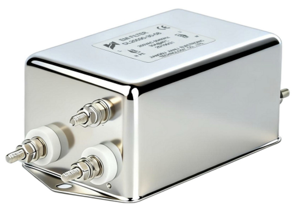
Selecting a 3-Phase EMI Filter requires verifying seven interdependent parameters: rated current, voltage class, leakage current, insertion loss, noise mode topology, installation geometry, and load compatibility. Incorrect specification causes compliance failures and accelerated component degradation.
1. Rated Current and Voltage Class: The Foundation of Filter Sizing
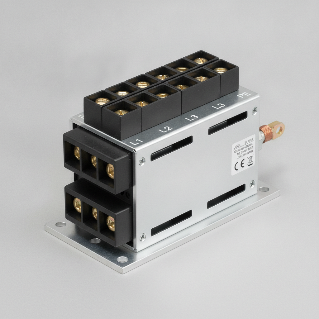
1.1 Why Rated Current Directly Impacts Attenuation Performance
Rated current is the single most misapplied parameter in 3-Phase EMI Filter selection.
- Operating a filter above its rated current saturates the common-mode choke core, collapsing inductance by 40–70%.
- Core saturation directly degrades insertion loss across the entire attenuation bandwidth.
- Derate by 20–25% for ambient temperatures exceeding 40°C per IEC 60939-3.
Key Rule: Filter rated current ≥ 1.25× maximum continuous load current.
1.2 Voltage Class and Dielectric Withstand
| Voltage Class | Typical Application | Dielectric Test Voltage |
|---|---|---|
| 250V AC (L-N) | Single-phase derived 3-phase | 1,500V AC / 1 min |
| 480V AC (L-N) | North American industrial | 2,000V AC / 1 min |
| 520V AC (L-N) | European 3×400V systems | 2,500V AC / 1 min |
| 690V AC (L-N) | Heavy industrial, marine | 3,000V AC / 1 min |
- Mismatch between system voltage and filter voltage class causes insulation breakdown within 500–2,000 operating hours.
- Always confirm line-to-neutral voltage, not line-to-line, against the filter datasheet rating.
2. Leakage Current Thresholds and Compliance Standards
Leakage current is the critical safety parameter for Industrial EMI Filter deployment, governed by grounding topology and end-use environment.
2.1 Regulatory Leakage Current Limits
| Standard | Application | Max Leakage Current |
|---|---|---|
| IEC 60950-1 | IT equipment | 3.5 mA (portable), 5 mA (fixed) |
| IEC 62368-1 | Audio/video, IT | 0.25 mA (touch current) |
| IEC 60204-1 | Industrial machinery | 10 mA (TN system) |
| UL 508A | Industrial control panels | 5 mA (general) |
| EN 60335-1 | Household/light commercial | 0.75 mA |
- Leakage current flows through Y-capacitors connecting line conductors to protective earth (PE).
- Higher Y-capacitor values improve common-mode attenuation but increase leakage current proportionally.
- For IT-connected equipment or medical-adjacent installations, specify low-leakage variants (≤1 mA).
2.2 Grounding System Impact
- TN-S systems: Full leakage current flows through PE conductor; standard filters acceptable.
- TT systems: Residual current devices (RCDs) may nuisance-trip with filters exceeding 3.5 mA total leakage.
- IT systems (floating): Y-capacitors create asymmetric ground faults; consult manufacturer before deploying standard Three Phase Power Filter designs.
3. Common-Mode vs. Differential-Mode Noise: Topology Selection Logic
Noise mode identification is mandatory before specifying a Three Phase Line Filter topology.
3.1 Noise Mode Characteristics
Common-Mode (CM) Noise:
- Flows identically on all phase conductors relative to ground.
- Generated by switching power supplies, VFDs, and IGBT inverters.
- Suppressed by common-mode chokes (toroidal wound, high-permeability ferrite) and Y-capacitors.
Differential-Mode (DM) Noise:
- Flows between phase conductors; returns on the same power path.
- Generated by rectifier front-ends, motor inrush, and capacitor bank switching.
- Suppressed by series inductors (DM chokes) and X-capacitors.
3.2 Filter Topology Comparison
| Topology | CM Attenuation | DM Attenuation | Typical Use Case |
|---|---|---|---|
| CM choke + Y-caps only | High (40–60 dB) | Low (<10 dB) | VFD output filters |
| DM inductors + X-caps only | Low (<10 dB) | High (30–50 dB) | Rectifier front-ends |
| Combined LC (standard) | Medium (30–50 dB) | Medium (20–40 dB) | General industrial |
| Multi-stage (2× LC) | High (50–80 dB) | High (40–70 dB) | Precision CNC, medical |
- Most industrial 3-Phase Filter products target combined CM+DM suppression.
- VFD applications generate predominantly CM noise; specify CM-optimized topologies with Y-capacitor values ≥ 470 nF per phase.
- Measure noise floor with a spectrum analyzer at 150 kHz–30 MHz before finalizing topology.
4. Insertion Loss and Installation Parameters
Insertion loss is the primary performance metric for any 3-Phase EMI Filter, but published datasheet values assume ideal laboratory conditions that rarely exist in field installations.
4.1 Parameters That Degrade Insertion Loss
Impedance Mismatch:
- CISPR 17 standard measures insertion loss with 50Ω source and load impedance.
- Real industrial impedances range from 0.1Ω (motor loads) to 500Ω+ (switching supplies).
- Actual field insertion loss can be 15–30 dB lower than datasheet values.
Ground Lead Length:
- Every 10 cm of PE ground lead adds approximately 10 nH inductance.
- At 10 MHz, 10 nH = 0.63Ω impedance, severely limiting high-frequency Y-capacitor effectiveness.
- Maximum PE lead length: 50 mm. Use shortest possible braided strap to chassis ground.
Physical Separation from Noise Source:
- Unshielded input and output cables running parallel over >150 mm re-couple attenuated noise back into the output.
- Maintain minimum 100 mm separation or use shielded conduit between filter input/output wiring.
Mounting Surface:
- Filters mounted on painted or non-conductive surfaces lose 10–20 dB of high-frequency attenuation.
- Direct metal-to-metal contact between filter chassis and equipment enclosure is mandatory.
4.2 Temperature Derating for Insertion Loss
- X-capacitors (polypropylene film) exhibit <5% capacitance drift from −40°C to +85°C; stable.
- Y-capacitors (Class X1/Y2 ceramic) show up to 15% capacitance reduction at 85°C.
- Common-mode choke inductance decreases 8–12% at 85°C due to ferrite permeability reduction.
5. VFD Compatibility and Attenuation Bandwidth Requirements
Variable Frequency Drives are the dominant noise source in industrial environments, and 3-Phase EMI Filter selection must align with VFD switching characteristics.
5.1 VFD Switching Frequency vs. Filter Bandwidth
| VFD Switching Frequency | Primary Harmonic Range | Required Filter -3dB Bandwidth |
|---|---|---|
| 2–4 kHz (legacy) | 6–50 kHz | 10 kHz – 1 MHz |
| 4–8 kHz (standard) | 12–100 kHz | 50 kHz – 5 MHz |
| 8–16 kHz (servo) | 24–200 kHz | 100 kHz – 10 MHz |
| 16–32 kHz (high-speed) | 48–400 kHz | 500 kHz – 30 MHz |
- CISPR 11 Class A industrial limits apply from 150 kHz; the filter must achieve required attenuation at this frequency.
- For servo drives operating at 16 kHz switching, specify filters with ≥40 dB insertion loss at 150 kHz.
5.2 Cable Length Between VFD and Filter
- Long motor cables (>10 m) increase parasitic capacitance to ground, raising CM leakage current.
- Install the 3-Phase EMI Filter at the VFD input, not the motor end.
- For cable lengths >50 m, add a dedicated output dV/dt filter in series with the motor cable.
5.3 DC Bus Considerations
- Some Three Phase Power Filter designs include DC-link capacitors for additional bulk energy storage.
- Verify filter capacitor inrush current rating against VFD DC bus pre-charge specifications.
- Mismatched inrush ratings cause capacitor failure within 10,000–50,000 switching cycles.
6. Real-World Application Scenarios
Scenario 1: CNC Machining Center with 15 kW Servo Drives
- Problem: CISPR 11 Class A failure at 1–10 MHz band.
- Solution: Multi-stage 3-Phase EMI Filter (2× LC), 25A rating, CM-optimized, 40 dB at 1 MHz.
- Result: 28 dB margin above Class A limit achieved; zero nuisance RCD trips.
Scenario 2: 75 kW VFD Pump Station, TT Grounding System
- Problem: 30 mA RCD nuisance tripping during VFD startup.
- Solution: Low-leakage Industrial EMI Filter (≤3.5 mA), reduced Y-capacitor topology, 100A rating.
- Result: Leakage current reduced from 28 mA to 2.8 mA; RCD tripping eliminated.
Scenario 3: Offshore Marine Power Distribution, 690V/50Hz
- Problem: Conducted emissions non-compliance under DNV GL class rules.
- Solution: 690V-rated Three Phase Line Filter, IP54 enclosure, 60A, marine-grade conformal coating.
- Result: Full compliance with IEC 60533 maritime EMC standard.
FAQ: 3-Phase EMI Filter Selection
Q: How does rated current affect 3-Phase EMI Filter attenuation performance?
Exceeding rated current saturates the CM choke core, reducing inductance 40–70% and collapsing insertion loss.
Q: What leakage current thresholds define Industrial EMI Filter compliance?
IEC 60204-1 allows 10 mA for industrial machinery; IEC 60950-1 limits IT equipment to 3.5–5 mA.
Q: How does common-mode vs. differential-mode noise impact Three Phase Line Filter topology?
CM noise requires Y-caps and CM chokes; DM noise requires X-caps and series DM inductors.
Q: Which installation parameters critically degrade Three Phase Power Filter insertion loss?
PE lead length >50 mm, parallel input/output cables, and non-metallic mounting surfaces each reduce insertion loss 10–20 dB.
Q: How do VFD switching frequencies determine 3-Phase EMI Filter attenuation bandwidth?
Higher switching frequencies (8–32 kHz) shift primary harmonics to 100–400 kHz, requiring filter bandwidth extending to 30 MHz.
Q: Can one 3-Phase Filter serve multiple VFDs on a shared bus?
Only if the filter’s rated current covers the total combined load; individual per-drive filtering is preferred for isolation.
Q: What certifications should an Industrial EMI Filter carry?
Minimum: CE marking (EN 60939-3), UL 508 for North America, and RoHS compliance for EU markets.
Q: Is IP rating relevant for EMI filter selection?
Yes. Washdown environments require IP54 minimum; outdoor installations require IP65 with UV-stable enclosures.
Conclusion and Engineering Recommendations
Selecting the correct 3-Phase EMI Filter for industrial applications requires a systematic seven-parameter verification process:
- Current rating: Apply 1.25× derating factor against maximum load current.
- Voltage class: Confirm line-to-neutral voltage, not line-to-line.
- Leakage current: Match to grounding system type and applicable standard.
- Noise mode: Measure CM vs. DM noise before specifying topology.
- Insertion loss: Validate against real load impedance, not 50Ω CISPR 17 test conditions.
- Installation: PE lead ≤50 mm, metal mounting, separated cable routing.
- VFD compatibility: Match attenuation bandwidth to drive switching frequency.
Engineers who skip pre-installation noise measurement and rely solely on datasheet insertion loss values consistently encounter field compliance failures. Invest in a conducted emissions pre-scan before finalizing three phase EMI filter selection to confirm adequate attenuation margin at 150 kHz–30 MHz.
References and Standards:
- IEC 60939-3: Passive filter units for electromagnetic interference suppression
- CISPR 11:2015+A2:2019: Industrial, scientific and medical equipment – RF disturbance characteristics
- CISPR 17:2011: Methods of measurement of the suppression characteristics of passive EMI filtering devices
- IEC 60204-1:2016: Safety of machinery – Electrical equipment of machines
- IEC 60529: Degrees of protection provided by enclosures (IP Code)
- MIL-STD-461G: Requirements for the control of electromagnetic interference
- EN 60939-3: European harmonized standard for passive EMC filter components