
Abstract
Motor drives — particularly variable frequency drives (VFDs) — are indispensable in modern industrial automation, yet they are among the most prolific sources of high-frequency electromagnetic interference on a plant network. The rapid switching transients inherent to pulse-width modulation (PWM) technology generate conducted emissions that propagate back through the supply network, corrupting sensitive instrumentation, triggering nuisance trips, and creating significant obstacles to regulatory certification.
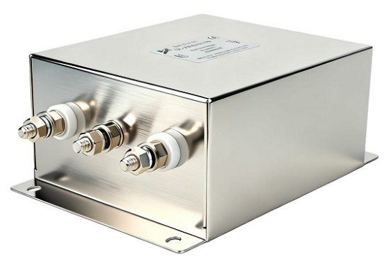
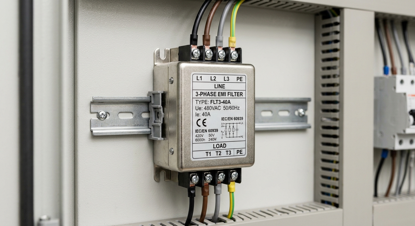
A 3-phase EMI filter is the primary engineering countermeasure for these emissions. Installed between the mains supply and the drive input, it attenuates both common-mode and differential-mode noise before it can reach the broader electrical infrastructure. For procurement engineers and system integrators, understanding why this component is non-negotiable — and how to select it correctly — is essential to delivering compliant, reliable drive systems on schedule and within budget. This article provides a structured technical and commercial framework for that decision.
1. How Motor Drives Generate EMI and Why It Matters
1.1 The EMI Emission Mechanism in Variable Frequency Drives (VFDs)
The core EMI problem in motor drives originates at the IGBT switching stage. Modern VFDs switch at carrier frequencies typically between 2 kHz and 16 kHz, with voltage rise times (dV/dt) in the range of 1–10 kV/µs. Each switching event injects a broadband noise pulse into both the motor cable and the supply network.
Two distinct noise paths are created:
- Differential-mode (DM) noise: Current flows between phase conductors, primarily generated by the rectifier stage and DC bus ripple. It is attenuated by differential-mode inductors and X-capacitors.
- Common-mode (CM) noise: Current flows simultaneously on all phase conductors relative to ground, driven by parasitic capacitance between the motor windings, cable shield, and chassis. CM noise is the dominant emission mechanism in VFD installations and requires common-mode chokes and Y-capacitors for effective suppression.
Conducted emissions from VFDs are measurable in the frequency range of 150 kHz to 30 MHz — precisely the band regulated by CISPR 11 and EN 55011. Without filtering, emission levels routinely exceed Class A limits by 20–40 dB in standard industrial installations.
1.2 Impact on Connected Equipment and Plant Networks
Unfiltered VFD emissions cause concrete operational damage across several vectors:
- Bearing currents: High-frequency CM currents circulate through motor bearings via the rotor shaft, causing electrostatic discharge (EDM) pitting and premature bearing failure — a well-documented failure mode in unfiltered installations.
- PLC and controller signal corruption: Conducted noise on the supply bus couples into 24 VDC control circuits, causing spurious I/O states, watchdog resets, and communication faults on fieldbus networks (PROFIBUS, EtherCAT, Modbus).
- Instrumentation interference: Precision sensors, encoders, and measurement systems sharing the same electrical panel are particularly vulnerable, leading to measurement errors and process instability.
- Nuisance RCD tripping: Common-mode leakage currents from unfiltered drives can trigger residual current devices, causing unplanned downtime in facilities with sensitive earth-fault protection.
The commercial consequence of these failure modes — unplanned production stoppages, warranty claims, and field service costs — far exceeds the cost of proper EMI filtration at the design stage.
2. Technical Architecture of a 3-Phase EMI Filter
2.1 Core Components and Attenuation Topology
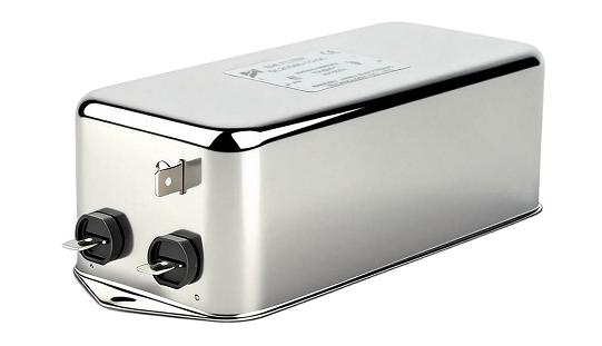
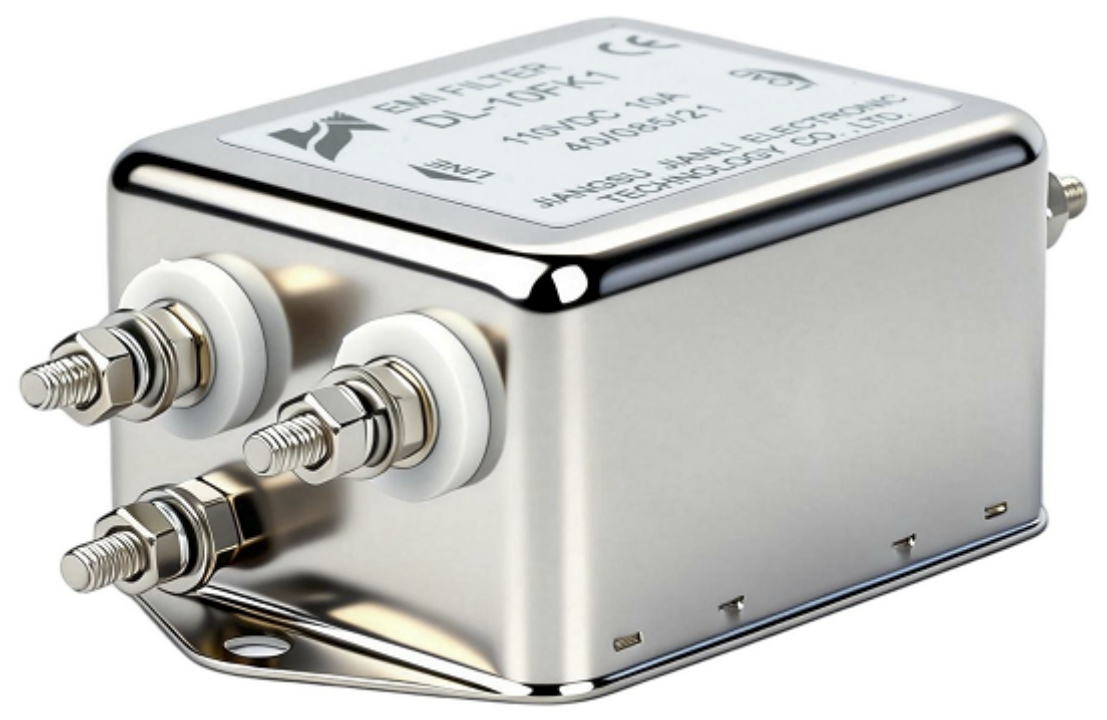
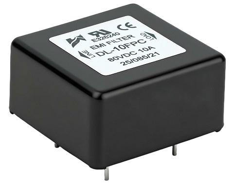
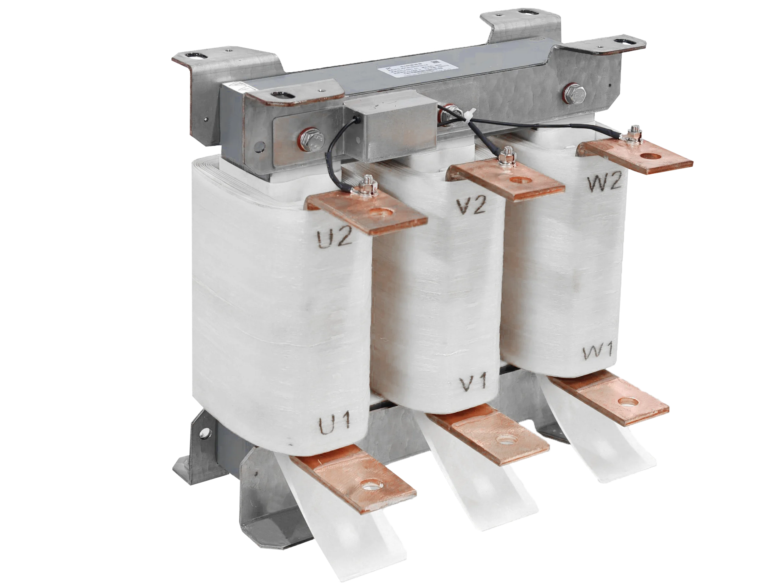
A 3-phase EMI filter for motor drive applications is a passive LC network optimized to present high impedance to high-frequency noise while remaining transparent to the 50/60 Hz fundamental. Its key internal elements are:
- Common-mode choke: A toroidal or E-core inductor wound with all three phase conductors. It presents high impedance to CM currents (which sum to a net flux in the core) while passing differential load currents with minimal voltage drop.
- Y-capacitors: Connected from each phase to the protective earth (PE). They provide a low-impedance return path for CM noise to ground, directly reducing CM voltage at the drive input terminals.
- X-capacitors: Connected phase-to-phase, they attenuate differential-mode noise by forming a low-pass filter with the differential-mode inductance.
- Differential-mode inductors: Provide additional DM attenuation, particularly important when the drive’s DC bus generates significant low-frequency ripple currents.
The combined insertion loss of a well-designed 3-phase EMI filter typically achieves 40–60 dB of CM attenuation and 30–50 dB of DM attenuation across the 150 kHz–30 MHz band. Insertion loss curves, provided in the filter datasheet, should be evaluated at the actual source and load impedances of the drive system — not just the standard 50 Ω CISPR test conditions.
2.2 Key Electrical Parameters and Selection Criteria
Correct filter selection requires matching several interdependent parameters to the specific drive installation:
| Parameter | Typical Range | Selection Guidance |
|---|---|---|
| Rated Current (A) | 6 A – 2000 A | Match to drive input RMS current with 10–20% margin |
| Operating Voltage | 480 V / 690 V AC | Must meet or exceed supply voltage class |
| Leakage Current (mA) | 1 mA – 300 mA | ≤3.5 mA for portable equipment; up to 300 mA for fixed industrial |
| Insertion Loss (dB) | 40–60 dB CM | Verify at actual drive impedance, not only 50 Ω |
| Temperature Derating | –25°C to +85°C | Apply manufacturer’s derating curve above 40°C |
| Mounting Form | DIN rail/chassis/busbar | Dictated by panel layout and cable routing requirements |
| Compatible Drive Power | 0.75 kW – 1 MW+ | Filter must handle inrush current at drive startup |
Critical note on leakage current: Y-capacitors that suppress CM noise also contribute to PE leakage current. In installations protected by residual current devices (RCDs), total leakage current — including contributions from all connected drives and filters — must remain below the RCD trip threshold. IEC 60364-4-41 and local wiring regulations define maximum permissible values.
Impedance matching is frequently overlooked. The drive’s input impedance varies with operating point. A filter optimized for a 50 Ω test environment may underperform when connected to a low-impedance drive rectifier. Specify filters validated against actual drive input impedance data where possible.
3. EMC Compliance Standards and Certification Requirements
3.1 Applicable Industrial EMC Standards
The primary standard governing motor drive EMC in industrial environments is IEC/EN 61800-3 (Adjustable Speed Electrical Power Drive Systems — EMC Requirements). It defines two installation environment categories:
- Category C2: Fixed professional installation, supply connection by qualified personnel. Corresponds broadly to CISPR 11 Class A limits.
- Category C3: Supply voltage >1000 V or rated current >400 A in the second environment. More permissive emission limits but stricter installation controls.
For CE marking of drive systems sold into the EU, compliance with EN 61800-3 (as a product-specific standard) satisfies the EMC Directive 2014/30/EU. Importantly, a drive that is compliant as a standalone unit may fail system-level compliance when installed with long motor cables — the 3-phase EMI filter is often the decisive component that bridges this gap.
CISPR 11 / EN 55011 applies to industrial, scientific, and medical equipment and sets the conducted emission limits (Class A: quasi-peak 79 dBµV at 150 kHz, falling to 73 dBµV at 30 MHz) against which filter performance is ultimately measured.
3.2 Filter Validation and Testing Methodology
Compliance verification follows a defined workflow:
- Pre-compliance screening: Conducted an emission scan using a Line Impedance Stabilization Network (LISN) per CISPR 16-1-2, with the drive running at representative load points (typically 50% and 100% rated torque).
- Filter insertion: Install the 3-phase EMI filter with cable routing per manufacturer guidelines. Cable separation between filter input and output is critical — parallel routing of filtered and unfiltered cables defeats attenuation.
- Post-filter verification: Re-run the conducted emission scan. Document margin against applicable limits (minimum 6 dB margin recommended for production variability).
- Leakage current measurement: Verify PE leakage current complies with IEC 60990 measurement method and applicable installation standard.
OEMs integrating third-party drives into machinery must conduct system-level EMC testing, not rely solely on the drive manufacturer’s component-level declaration. The 3-phase EMI filter, correctly selected and installed, is the primary tool for achieving and documenting that compliance.
4. Application Scenarios and Commercial Value
4.1 Typical Industrial Deployment Environments
3-phase EMI filters for motor drives are deployed across a broad range of industrial sectors:
- CNC machine tools: High-precision servo and spindle drives demand extremely low noise floors to prevent encoder interference and axis positioning errors.
- HVAC systems: Variable-speed pump and fan drives in commercial buildings require CE marking and must not interfere with building management system (BMS) communications.
- Conveyor and material handling: Multiple drives sharing a common supply bus create cumulative emission levels that only system-level filtering can adequately address.
- Pump and compressor applications: Long cable runs between drive and motor amplify CM emissions; a correctly rated filter at the drive input is mandatory for compliance.
- Renewable energy inverters: Grid-tied solar and wind inverters face stringent conducted emission requirements under EN 61000-3-2 and EN 55011, making high-performance 3-phase filtering essential.
4.2 Total Cost of Ownership and Risk Mitigation
The commercial case for specifying a 3-phase EMI filter is straightforward when total cost of ownership is evaluated:
- Downtime avoidance: A single unplanned production stoppage caused by EMI-induced PLC corruption or nuisance RCD tripping can cost multiples of the filter’s purchase price in lost output.
- Certification cycle acceleration: Systems pre-fitted with correctly specified filters typically pass EMC compliance testing on the first attempt, avoiding costly re-test cycles and project schedule delays.
- Warranty protection: Drive manufacturers frequently condition warranty coverage on the installation of an approved EMI filter. Non-compliance voids warranty claims.
- Reduced re-engineering risk: Retrofitting EMI filters after system commissioning is significantly more expensive than specifying them at the design stage, due to panel space constraints and additional wiring labor.
FAQ
Q1: How do I select the correct 3-phase EMI filter current rating for my motor drive system?
Select the filter’s rated current based on the drive’s maximum input RMS current at full load, not the motor nameplate current. Apply a minimum 10–20% derating margin and consult the manufacturer’s temperature derating curve if the installation ambient exceeds 40°C. For drives with high inrush current at startup, verify the filter’s peak current withstand rating.
Q2: What is the maximum allowable leakage current for a 3-phase EMI filter in an RCD-protected industrial installation?
IEC 60364-4-41 permits up to 3.5 mA leakage per circuit for equipment protected by a 30 mA RCD. For fixed industrial machinery on dedicated circuits, leakage up to 300 mA is permissible under EN 61800-3, provided the installation uses a Type B RCD or an isolation transformer. Always sum leakage contributions from all connected filters and drives on the protected circuit.
Q3: Can a single 3-phase EMI filter serve multiple drives sharing the same supply bus?
A single upstream filter can provide common-mode attenuation for multiple drives, but its current rating must cover the total combined input current of all connected drives simultaneously. Additionally, inter-drive interference through the shared DC bus is not addressed by a single upstream filter — individual drive-level filtering may still be required for high-sensitivity applications.
Conclusion
A 3-phase EMI filter is not an optional accessory — it is a critical system component for any motor drive installation that must deliver reliable operation, protect sensitive plant equipment, and achieve defensible EMC compliance. The conducted emissions generated by PWM switching are predictable, well-characterized, and effectively suppressed by a correctly specified filter. Conversely, the costs of ignoring this requirement — failed compliance testing, unplanned downtime, voided warranties, and premature equipment failure — are disproportionately high relative to the filter’s procurement cost.
For procurement engineers and system integrators, the decision framework is clear: specify the 3-phase EMI filter at the design stage, match it to the drive’s electrical parameters and installation environment, and validate performance against the applicable IEC/EN standards. This single design decision delivers measurable returns across the full operational lifecycle of the drive system.