
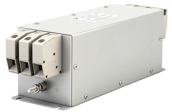
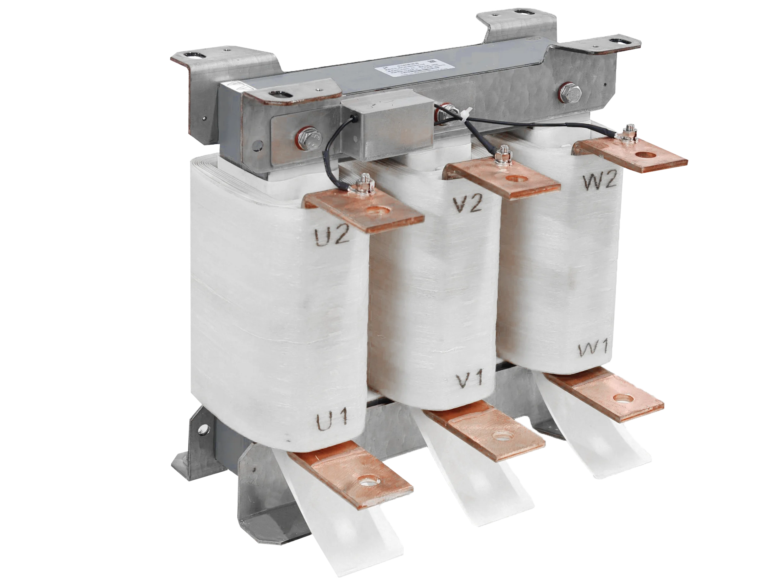
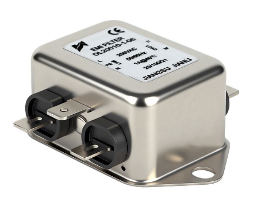
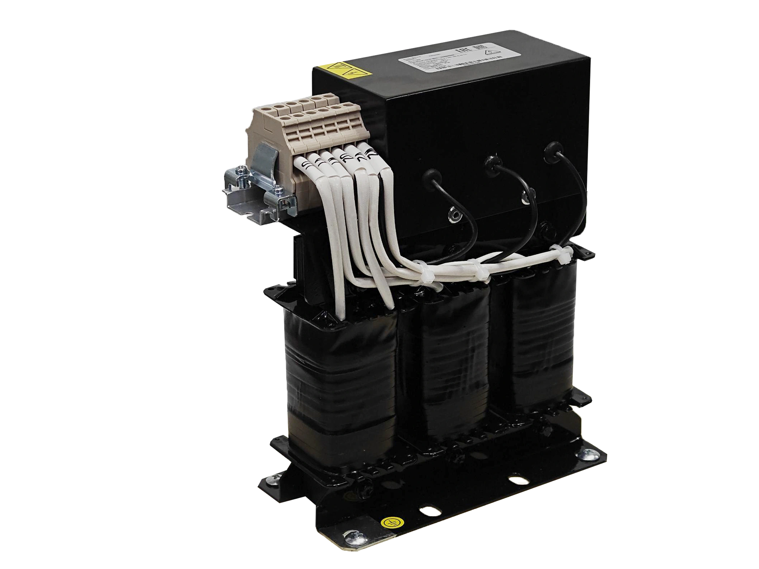
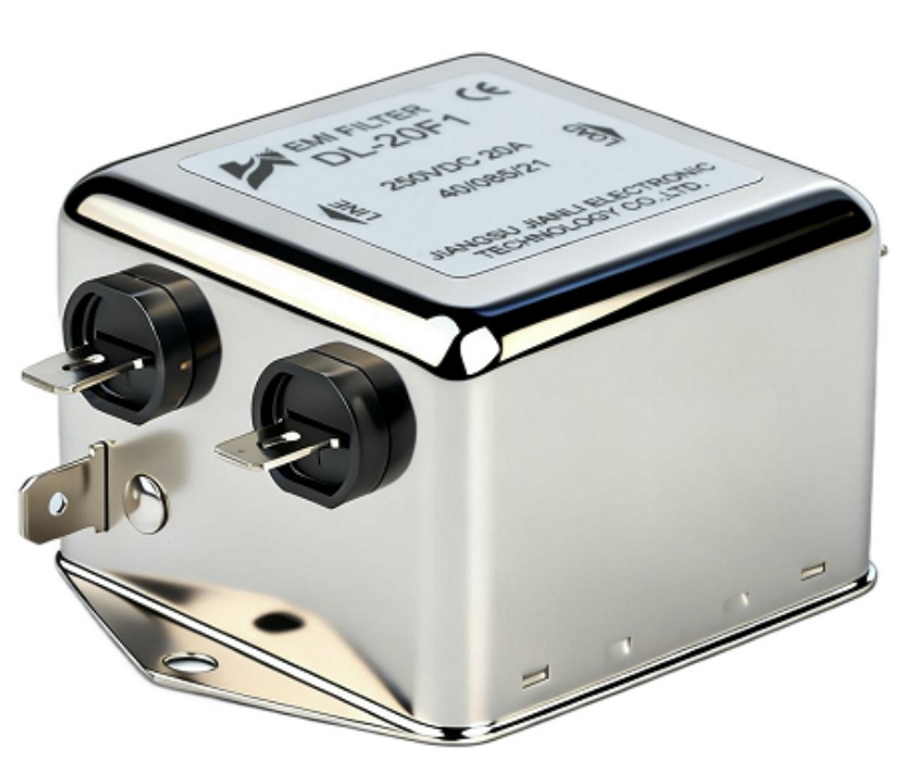
A DC filter for EV charging systems suppresses conducted and radiated electromagnetic interference generated on the DC output side of power converters. It protects vehicle electronics, ensures regulatory compliance, and maintains stable charging performance in high-power DC fast charging environments.
What Is a DC Filter for EV Charging Systems?
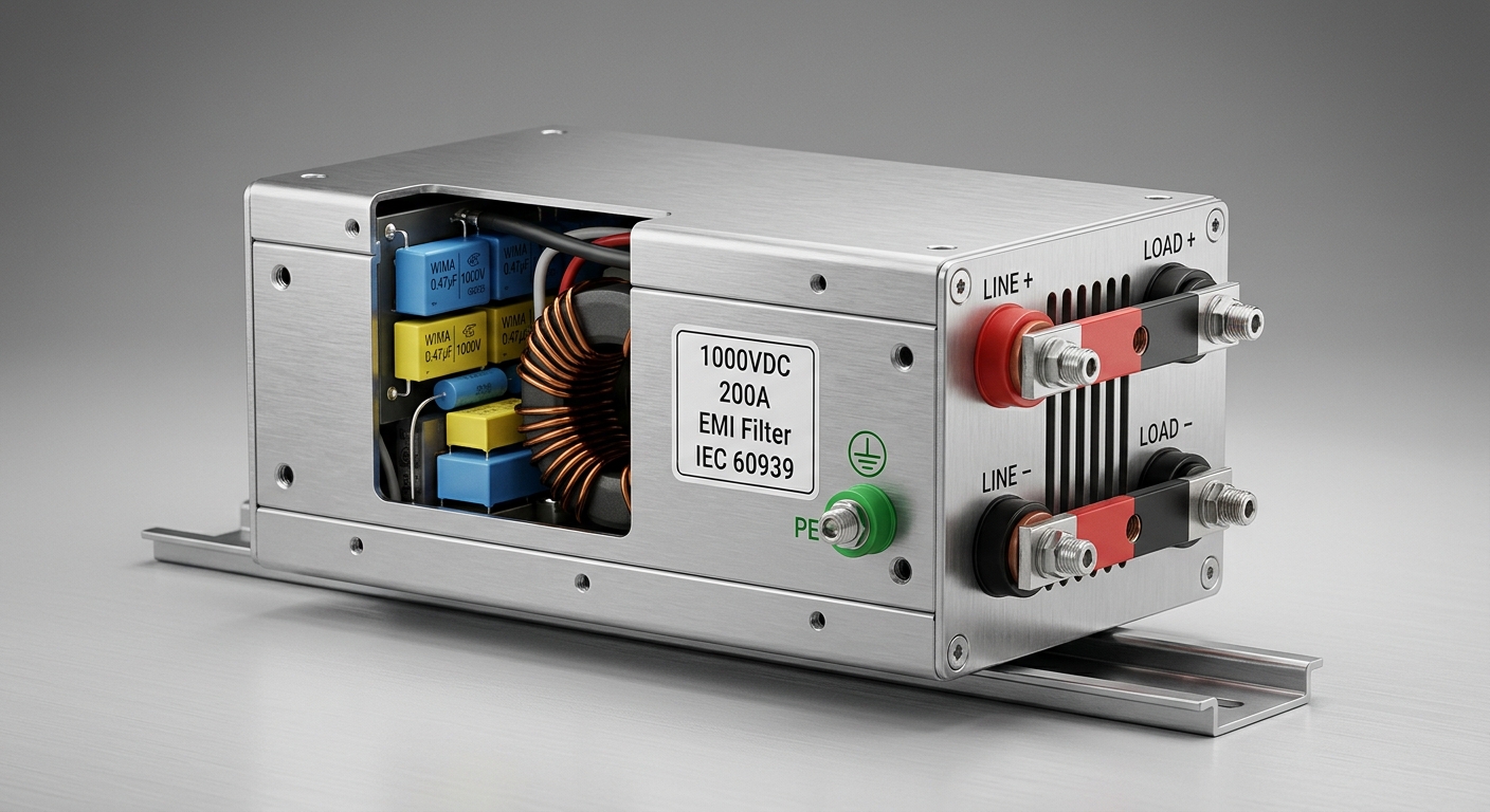
Definition and Functional Role
A DC filter for EV charging systems is a passive or active filtering network installed on the direct-current output path of an EV charger. Its primary function is to attenuate high-frequency noise generated by power switching components—typically IGBTs or SiC MOSFETs operating at 20–100 kHz switching frequencies.
Core functions:
- Suppress conducted EMI on the DC bus (150 kHz–30 MHz range)
- Reduce common-mode (CM) and differential-mode (DM) noise simultaneously
- Protect the EV battery management system (BMS) from high-frequency transients
- Prevent noise from coupling back into the AC grid
Why DC-Side Filtering Is Distinct from AC-Side Filtering
| Parameter | AC Input Filter | DC Output Filter |
|---|---|---|
| Operating voltage | 200–480 VAC | 200–1000 VDC |
| Noise frequency range | 150 kHz–30 MHz | 150 kHz–30 MHz |
| Impedance requirement | Matched to grid | Matched to battery load |
| Insulation class | Standard | High-voltage DC rated |
| Leakage current concern | Moderate | Critical (BMS sensitivity) |
DC-side EMI filtering for EV charging systems faces unique challenges: the load impedance is dynamic (battery state-of-charge varies), voltage levels reach 800–1000 V in next-generation chargers, and DC insulation requirements are stricter than equivalent AC systems.
Key Components Inside a DC EMI Filter
- Common-mode choke (CMC): Wound on high-permeability nanocrystalline or ferrite cores; attenuates CM noise by 40–60 dB
- X-capacitors (DM): Film capacitors (0.1–10 µF) placed line-to-line for differential-mode suppression
- Y-capacitors (CM): Ceramic or film capacitors (1–100 nF) placed line-to-ground; leakage current must remain below 3.5 mA per IEC 60950
- Damping resistors: Prevent resonance peaks in the filter’s insertion loss curve
How Does a DC EMI Filter Reduce Noise in EV Fast Chargers?
Conducted EMI Suppression Mechanism
DC fast chargers generate switching noise through two primary mechanisms:
- Differential-mode (DM) noise: Current flows in opposite directions on positive and negative DC rails; caused by inductor current ripple
- Common-mode (CM) noise: Current flows in the same direction on both rails relative to ground; caused by parasitic capacitance between switching nodes and chassis
Attenuation pathway:
- CM choke presents high impedance (>1 kΩ at 1 MHz) to CM currents
- X-capacitors provide low-impedance return path for DM noise
- Y-capacitors shunt CM currents to chassis ground before they reach the cable
Insertion Loss Performance Data
| Frequency | Typical CM Attenuation | Typical DM Attenuation |
|---|---|---|
| 150 kHz | 20–30 dB | 15–25 dB |
| 1 MHz | 40–60 dB | 35–50 dB |
| 10 MHz | 50–70 dB | 45–65 dB |
| 30 MHz | 40–55 dB | 40–55 dB |
Data based on industry-standard filter testing per CISPR 17 and IEC 61000-4-6.
How DC-Side Noise Suppression Protects Vehicle Systems
- BMS protection: Switching transients above 1 V peak can trigger false BMS fault codes
- CAN bus interference: Unfiltered DC lines act as antennas, coupling noise into vehicle communication networks
- Thermal management: Reduced EMI lowers the risk of interference with EV thermal control modules
Effective conducted EMI suppression in EV chargers requires the filter’s insertion loss to exceed the noise margin by at least 6 dB across the full CISPR 32 / CISPR 25 measurement bandwidth.
Where Should a DC Filter Be Installed in an EV Charging System?
Optimal Placement Principles
Correct installation position directly determines DC-side EMI filtering for EV charging systems effectiveness.
Recommended placement:
- Immediately after the DC/DC converter output stage
- Before the output contactor and metering shunt
- As close as possible to the DC output terminal (within 150 mm)
- Physically separated from high-current AC busbars by minimum 50 mm
System Architecture Integration
[AC Grid] → [AC/DC Rectifier] → [DC/DC Converter] → [DC EMI Filter] → [Output Contactor] → [DC Charging Cable] → [EV Battery]
Installation rules:
- Filter chassis must be bonded to station protective earth (PE) with <0.1 Ω impedance
- Input/output leads must not run parallel for more than 50 mm to prevent coupling bypass
- Shield the filter enclosure if ambient switching frequencies exceed 500 kHz
- Use separate conduit for filtered and unfiltered DC wiring
Grounding and Shielding Requirements
| Installation Factor | Specification |
|---|---|
| PE bonding resistance | < 0.1 Ω |
| Minimum separation from AC bus | 50 mm |
| Cable entry/exit separation | Opposite sides of filter |
| Enclosure material | Aluminum alloy or steel (IP54 minimum) |
| Torque on ground terminal | Per manufacturer spec (typically 2–4 Nm) |
How Do You Choose the Right DC Filter for an EV Fast Charger?
Critical Selection Parameters
EMI filter selection for DC fast chargers requires matching five key parameters:
- Rated DC voltage: Must exceed maximum system voltage with ≥20% margin (e.g., 1200 VDC rating for 1000 V systems)
- Rated current: Continuous current rating ≥ maximum output current; derate by 20% for ambient temperatures above 40°C
- Insertion loss profile: Verify attenuation meets CISPR 32 Class B limits across 150 kHz–30 MHz
- Leakage current: ≤3.5 mA for public charging stations per IEC 61851-23
- Operating temperature: –40°C to +85°C for outdoor DCFC installations
Comparison: Filter Technologies for EV Applications
| Filter Type | Voltage Range | Current Range | Best Application |
|---|---|---|---|
| LC passive filter | Up to 1500 VDC | 10–500 A | Standard DCFC (50–350 kW) |
| Active EMI filter | Up to 800 VDC | 10–100 A | Space-constrained OBC/EVSE |
| Hybrid LC + active | Up to 1000 VDC | 50–300 A | High-power, high-density chargers |
| Feedthrough capacitor | Up to 2000 VDC | 1–50 A | Signal-level DC lines |
Long-Tail Specification Checklist
- [ ] Confirm DC power filter for EV charging equipment carries UL 1283, IEC 60939, or equivalent certification
- [ ] Verify capacitor technology: film capacitors preferred over electrolytic for DC applications (no polarity risk, longer lifespan >100,000 hours)
- [ ] Check creepage and clearance distances meet IEC 60664-1 for 1000 VDC (minimum 14 mm creepage for Pollution Degree 2)
- [ ] Request CISPR 17 insertion loss test reports from manufacturer
- [ ] Confirm IP rating matches deployment environment (IP54 for indoor, IP65 for outdoor)
Can a DC Filter Help an EV Charger Meet EMC Requirements?
Applicable EMC Standards for EV Charging Equipment
EMC design for EV charging equipment is governed by multiple overlapping standards:
| Standard | Scope | Emission Limit Class |
|---|---|---|
| CISPR 32 | Multimedia/EV equipment emissions | Class A (industrial), Class B (residential) |
| IEC 61851-21-2 | EV conductive charging EMC | DC charging systems |
| IEC 61000-6-4 | Industrial emission standard | Class A |
| FCC Part 15 | US market radiated/conducted emissions | Class A/B |
| GB/T 18487.1 | China EV charging standard | — |
Compliance Pathway Using DC Filters
A properly selected high-voltage DC EMI filter for EV charging can reduce conducted emissions by 20–60 dB, enabling compliance with CISPR 32 Class B limits (quasi-peak limit: 66 dBµV at 150 kHz, 60 dBµV at 500 kHz–5 MHz, 50 dBµV at 30 MHz).
Compliance design steps:
- Conduct pre-compliance EMC scan on unfiltered DC output
- Identify dominant noise frequencies and modes (CM vs. DM)
- Select filter with insertion loss exceeding noise floor by ≥6 dB margin
- Verify leakage current compliance post-installation
- Conduct final CISPR 32 / IEC 61851-21-2 type test at accredited lab
Real-World Application Scenarios
Scenario 1 – 150 kW CCS DCFC Station:
A European charging network operator integrated a 1000 VDC / 200 A DC EMI filter immediately post-converter. Pre-filter conducted emissions at 1 MHz measured 85 dBµV; post-filter measurements dropped to 42 dBµV—achieving CISPR 32 Class B compliance with 18 dB margin.
Scenario 2 – 350 kW Ultra-Fast Charger (800V Platform):
An OEM deploying 800 V architecture selected a hybrid LC filter rated 900 VDC / 400 A. The filter reduced CM noise by 52 dB at 500 kHz, preventing BMS false-fault events that had occurred during initial prototype testing.
Scenario 3 – Bidirectional V2G Charger:
A V2G system integrator used a symmetrical DC EMI filter supporting bidirectional current flow (±200 A). This eliminated grid-side harmonic injection caused by vehicle-to-grid power reversal, meeting IEC 61000-3-12 grid compatibility requirements.
FAQ: DC Filter for EV Charging Systems
Q1: What Is a DC Filter for EV Charging Systems?
A passive network that suppresses DC-side conducted and radiated EMI in EV chargers.
Q2: How Does a DC EMI Filter Reduce Noise in EV Fast Chargers?
CM chokes and capacitors attenuate common-mode and differential-mode switching noise.
Q3: Where Should a DC Filter Be Installed in an EV Charging System?
Directly after the DC/DC converter output, before the output contactor.
Q4: How Do You Choose the Right DC Filter for an EV Fast Charger?
Match voltage rating, current rating, insertion loss profile, and leakage current to system specs.
Q5: Can a DC Filter Help an EV Charger Meet EMC Requirements?
Yes—a properly rated filter enables CISPR 32 Class B and IEC 61851-21-2 compliance.
Q6: What voltage ratings are available for DC EMI filters in EV applications?
Standard ratings range from 500 VDC to 1500 VDC for current EV charging platforms.
Q7: What is the typical insertion loss of a DC EMI filter at 1 MHz?
40–60 dB common-mode attenuation at 1 MHz for industrial-grade DC filters.
Q8: Do DC filters affect charging efficiency?
Minimal impact; typical resistive losses are <0.1% of rated power at full load.
Conclusion
A DC filter for EV charging systems is a non-negotiable component in any high-power EV charging design. It directly enables:
- EMC compliance with CISPR 32, IEC 61851-21-2, and FCC Part 15
- System reliability by protecting BMS and vehicle communication networks
- Grid stability by preventing noise from coupling back to the AC supply
Selection priority: Match rated DC voltage (with ≥20% margin), verify CISPR 17 insertion loss data, confirm leakage current ≤3.5 mA, and validate IP rating for the deployment environment.
Engineering recommendation: Always conduct pre-compliance EMC scanning before final filter selection. A 6 dB compliance margin above the regulatory limit is the industry minimum standard for robust, production-ready EV charging equipment.
For EV charger OEMs, system integrators, and EMC engineers, specifying the correct DC EMI filter for high-power EV chargers at the design stage—rather than as a retrofit—reduces certification risk, shortens time-to-market, and ensures long-term field reliability.
References and Standards
- CISPR 32:2015 – Electromagnetic compatibility of multimedia equipment – Emission requirements
- IEC 61851-21-2:2018 – Electric vehicle conductive charging system – EMC requirements
- IEC 60939-3 – Passive filter units for electromagnetic interference suppression
- IEC 61000-6-4:2018 – Generic standards – Emission standard for industrial environments
- CISPR 17:2011 – Methods of measurement of the suppression characteristics of passive EMC filtering devices
- IEC 60664-1:2020 – Insulation coordination for equipment within low-voltage supply systems
- FCC 47 CFR Part 15 – Radio frequency devices
- GB/T 18487.1-2023 – Electric vehicle conductive charging system (China national standard)
- SAE J2894/2 – Power quality requirements for plug-in electric vehicle chargers